PSMPC – Pulse-step model predictive controller
Block SymbolLicensing group: ADVANCED

Function Description
The PSMPC block can be used for control of hardly controllable linear time-invariant systems
with manipulated value constraints (e.g. time delay or non-minimum phase systems). It is
especially well suited for the case when fast transition without overshoot from one level of
controlled variable to another is required. In general, the PSMPC block can be used where the
PID controllers are commonly used.

The PSMPC block is a predictive controller with explicitly defined constraints on the amplitude of manipulated variable.
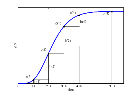
The prediction is based on the discrete step response is used. The figure above shows how to obtain the discrete step response and the discrete impulse response with sampling period from continuous step response. Note that must be chosen such that , where is the time to reach 95 % of the final steady state value.
For stable, linear and t-invariant systems with monotonous step response it is also possible to use the moment model set approach [4] and describe the system by only 3 characteristic numbers , , and , which can be obtained easily from a very short and simple experiment. The controlled system can be approximated by first order plus dead-time system
| (7.1) |
or second order plus dead-time system
| (7.2) |
with the same characteristic numbers. The type of approximation is selected by the imtype parameter.
To lower the computational burden of the open-loop optimization, the family of admissible control sequences contains only sequences in the so-called pulse-step shape depicted below:

Note that each of these sequences is uniquely defined by only four numbers , and , where is the control horizon and stand for the given lower and upper limit of the manipulated variable. The on-line optimization (with respect to , , and ) minimizes the criterion
| (7.3) |
where is the predicted control error at time over the coincidence interval , are the differences of the control signal over the interval and penalizes the changes in the control signal. The algorithm used for solving the optimization task (7.3) combines brute force and the least squares method. The value is determined using the least squares method for all admissible combinations of , and and the optimal control sequence is selected afterwards. The selected sequence in the pulse-step shape is optimal in the open-loop sense. To convert from open-loop to closed-loop control strategy, only the first element of the computed control sequence is applied and the whole optimization procedure is repeated in the next sampling instant.
The parameters , , , and in the criterion (7.3) take the role of design parameters. Only the last parameter is meant for manual tuning of the controller. In the case the model in the form (7.1) or (7.2) is used, the parameters and are determined automatically with respect to the and characteristic numbers. The controller can be then effectively tuned by adjusting the characteristic numbers , and .
Warning
It is necessary to set the sr array sufficiently large to avoid Matlab/Simulink crash when
using the PSMPC block for simulation purposes. Especially when using FOPDT or SOPDT
model, the sr array size must be greater than the length of the internally computed discrete
step response.
Inputs
sp | Setpoint variable | Double (F64) |
pv | Process variable | Double (F64) |
tv | Tracking variable (applied control signal) | Double (F64) |
hv | Manual value | Double (F64) |
MAN | Manual or automatic mode | Bool |
|
|
|
Outputs
mv | Manipulated variable (controller output) | Double (F64) |
dmv | Controller velocity output (difference) | Double (F64) |
de | Deviation error | Double (F64) |
SAT | Saturation flag | Bool |
|
|
|
pve | Predicted process variable based on the controlled process model | Double (F64) |
iE | Error code | Long (I32) |
|
|
|
Parameters
nc | Control horizon length () 5 | Long (I32) |
np1 | Start of coincidence interval () 1 | Long (I32) |
np2 | End of coincidence interval () 10 | Long (I32) |
lambda | Control signal penalization coefficient () 0.05 | Double (F64) |
umax | Upper limit of the controller output () 1.0 | Double (F64) |
umin | Lower limit of the controller output () -1.0 | Double (F64) |
imtype | Controlled process model type 3 | Long (I32) |
|
|
|
kappa | Static gain () 1.0 | Double (F64) |
mu | Resident time constant () 20.0 | Double (F64) |
sigma | Measure of the system response length () 10.0 | Double (F64) |
nmax | Reserved size of the array 10 10000 32 | Long (I32) |
sr | Discrete step response sequence () [0 0.2642 0.5940 0.8009 0.9084 0.9596 0.9826 0.9927 0.9970 0.9988 0.9995] | Double (F64) |
[Previous] [Back to top] [Up] [Next]
2023 © REX Controls s.r.o., www.rexygen.com