Raspberry Pi driver for the REXYGEN system
(the RPiDrv module)
User guide
2023-12-15
Plzeň (Pilsen), Czech Republic
Contents
1.1 Introduction
1.2 System requirements
1.3 Installation of the driver on the host computer
1.4 Installation of the driver on the target device (Raspberry Pi)
2 Including the driver in the project
2.1 Adding the RPiDrv driver
2.2 Connecting the inputs and outputs in the control algorithm
2.2.1 GPIO pins of the Raspberry Pi
2.2.2 The PiFace Digital expansion board
2.2.3 The UniPi v1.1 expansion board
2.2.4 Pigeon PLCs
2.2.5 The Intellisys PIO expansion board
3 Troubleshooting
Chapter 1
The RPiDrv driver and the REXYGEN system
1.1 Introduction
This manual describes the RPiDrv driver for working with the Raspberry Pi (Raspberry Pi is a registered trademark of the Raspberry Pi Foundation.) minicomputer [1] within the REXYGEN system. The driver supports GPIO pins of the Raspberry Pi itself. Both input and output modes are supported.
The driver also supports the UniPi v1.1 [2] and PiFace Digital 1/2 [3] expansion boards as well as Pigeon PLCs [4] based on Raspberry Pi Compute Module. The driver was developed by the REX Controls company.
1.2 System requirements
The RPiDrv driver can be used on all Raspberry Pi models which does have a network adapter (LAN / WAN).
In order to use the driver, the host computer (development) and the target computer (runtime) must have the following software installed:
|
Host computer |
|
|
Operating system |
one of the following: Windows 10/11, GNU/Linux |
|
Development tools |
version of the REXYGEN system development tools for corresponding operating system |
|
Target device |
|
|
REXYGEN system |
version for Raspberry Pi with the Raspberry OS distribution of GNU/Linux (Any other Debian-based distribution should work as well.) |
|
IO driver |
version for Raspberry Pi |
|
|
|
|
|
|
1.3 Installation of the driver on the host computer
The RPiDrv driver is included in the installation package of the Development tools of the
REXYGEN system. It is necessary to select the corresponding package in the installer. The
REXYGEN system typically installs to the
C:\Program Files\REX Controls\REX <version> folder.
The following files are copied to the installation folder:
- Bin\RPiDrv_H.dll – Configuration part of the RPiDrv driver.
- Doc\PDF\ENGLISH\RPiDrv_ENG.pdf – This user manual.
1.4 Installation of the driver on the target device (Raspberry Pi)
If there is no RexCore runtime module installed on your Pi, install it first using the Getting started guide of REXYGEN [5]. The installation includes all necessary drivers including RPiDrv.
If you want to install RPiDrv separately, it can be done from the command line of
Raspberry Pi using the command
sudo apt-get install rex-rpidrvt
Chapter 2
Including the driver in the project
The driver is included in the project as soon as the driver is added to the project main file and the inputs and outputs are connected in the control algorithms.
2.1 Adding the RPiDrv driver
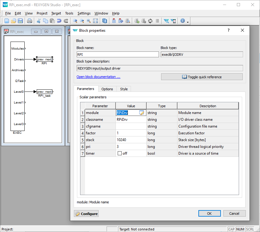
The project main file with the RPiDrv driver included is shown in Figure 2.1.
There is one block which must be added to the project to include the driver. A block of type IODRV connected to the Drivers output of the main EXEC block. The four most important parameters are:
- module – name of the module linked to the driver, in this case RPiDrv – the name is CASE SENSITIVE!
- classname – class of the driver – the name is CASE SENSITIVE!
- RPiDrv – Raspberry Pi GPIO, PiFace Digital expansion board (Obsolete device, no support provided. It is recommended to use the Monarco HAT instead.)
- UnpDrv – UniPi v1.1 expansion board
- PgnDrv – Pigeon PLCs1
- PioDrv – Intellisys PIO platform1
- cfgname – name of the driver configuration file, but this driver does not use any so leave it blank
- factor – multiple of the EXEC block’s tick parameter defining the driver’s task execution period
The name of this block (see Fig. 2.1), is the prefix of all input and output signals provided by this driver. It is recommended to rename the IODRV block according to the used platform:
- RPI – Raspberry Pi GPIO, PiFace Digital expansion board
- UNP – UniPi expansion board
- PGN – Pigeon PLCs
The above mentioned parameters of the IODRV function block are configured in REXYGEN Studioprogram. The configuration dialog is shown also in Fig. 2.1.
2.2 Connecting the inputs and outputs in the control algorithm
The inputs and outputs of the driver must be interconnected with the individual tasks (.mdl files). The individual tasks (QTASK or TASK blocks) are connected to the QTask, Level0,…, Level3 outputs of the main EXEC block.
2.2.1 GPIO pins of the Raspberry Pi
Necessary IODRV block configuration for Raspberry Pi GPIO:
- Block name – RPI
- module – RPiDrv
- classname – RPiDrv
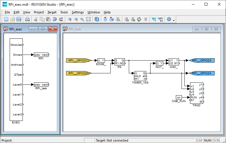
The inputs and outputs of the RPiDrv driver can be accessed as shown in Fig. 2.2.
One block of the From type allowing the user to read one input has the Goto tag set to RPI__GPIO21U, while the other has this tag set to RPI__GPIO22U. The number in the flag corresponds with the GPIO pin number and the U letter activates the pull-up resistor. The block of Goto type allowing the user to set (write) one output has the Goto tag) set to RPI__GPIO23, the other output is accessed via the RPI__GPIO24 flag. The blocks always have the RPI prefix right at the beginning of the tag followed by two _ characters (underscore).
Similarly for other pins we can use e.g. the flags:
- Goto, RPI__GPIO22 – digital output 22
- Goto, RPI__GPIO23H – digital output 23, which is set to logical 1 (HIGH, ON) immediately upon initialization
- Goto, RPI__PWM18 – PWM output on pin 18
- From, RPI__GPIO7U – digital input 7 with internal pull-up resistor
- From, RPI__GPIO8D – digital input 8 with internal pull-down resistor
- From, RPI__GPIO21 – digital input 21 without any internal pull-up/down resistor
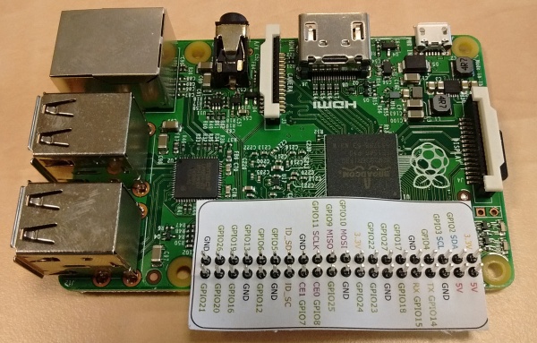
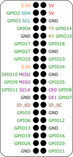
In general, the link to a particular GPIO pin consists of the driver name RPI, two underscores __, pin mode (GPIO or PWM), pin number and an optional symbol U for internal pull-up or D for internal pull-down in inputs and H or L for initial state in outputs. The pin numbering on Raspberry Pi is shown in Fig. 2.3.
All the input and output flags for the Raspberry Pi GPIO pins are contained in an example project 0120-00_IO_Flags.
Visit the http://elinux.org/RPi_Low-level_peripherals webpage for detailed information about individual GPIO pins.
2.2.2 The PiFace Digital expansion board
Necessary IODRV block configuration for PiFace Digital:
- Block name – RPI
- module – RPiDrv
- classname – RPiDrv
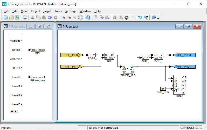
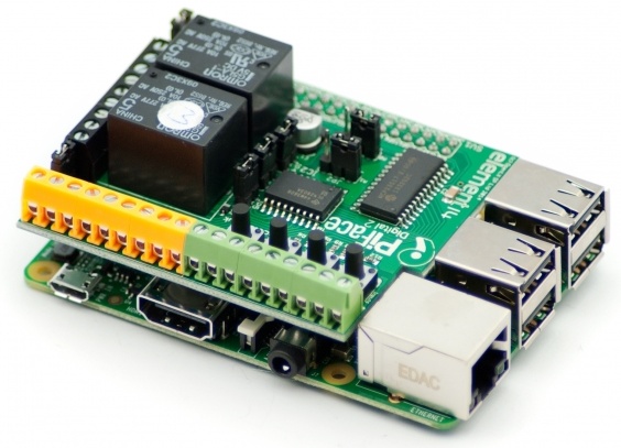
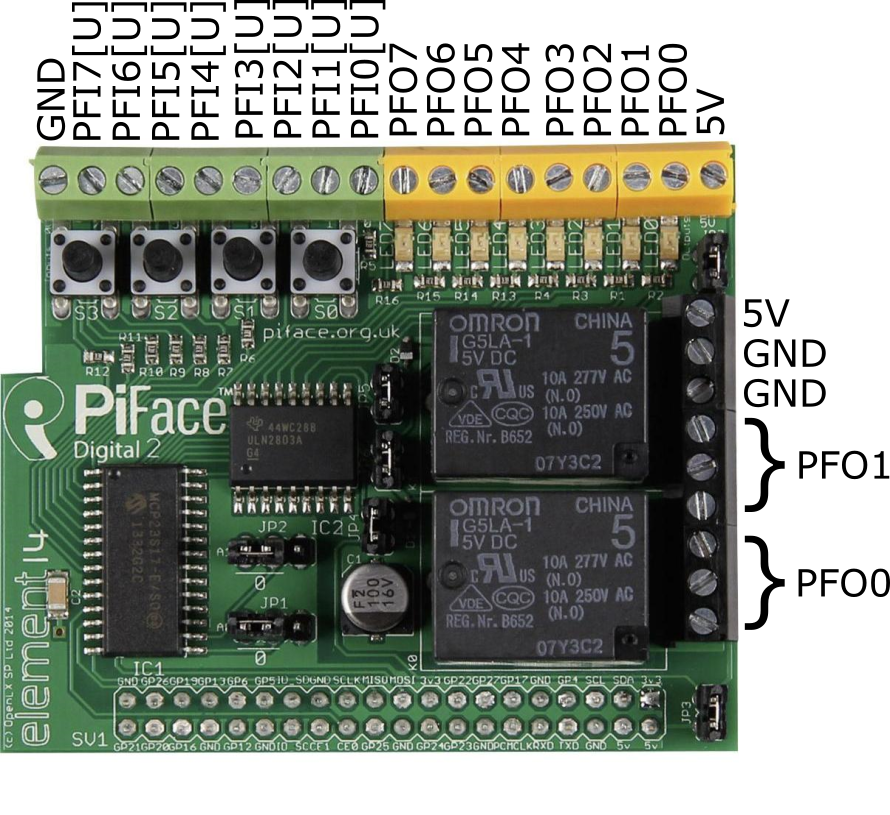
Because the inputs and outputs of the board are strictly separated, the input flags contain PFI string and the output ones contain PFO string as shown in Fig. 2.4. Similarly to the GPIO pins, the pull-up resistors in inputs can be activated by the optional character U in the signal name. There are no pull-down resistors available on the PiFace Digital. The numbering of terminals on the PiFace Digital expansion board is shown in Fig. 2.5.
All the input and output flags for the PiFace Digital expansion board are contained in an example project 0124-00_IO_Flags.
The numbering of the screw terminals of the PiFace Digital is depicted in Fig. 2.5.
It is also possible to read/write all eight inputs/outputs of PiFace Digital at once. This is faster than working with the individual signals. In that case the user must use the INOCT and OUTOCT blocks named RPI__PFI and RPI__PFO respectively.
Multiple PiFace Digital boards
It is assumed by default, that the PiFace Digital board is configured to have the address 0. If it is not the case, the address must be included in the input/output flag. E.g. RPI__PFO3C2 refers to the 4th output of the PiFace Digital card with address 2.
2.2.3 The UniPi v1.1 expansion board
Necessary IODRV block configuration for UniPi v1.1 expansion board:
- Block name – UNP
- module – RPiDrv
- classname – UnpDrv
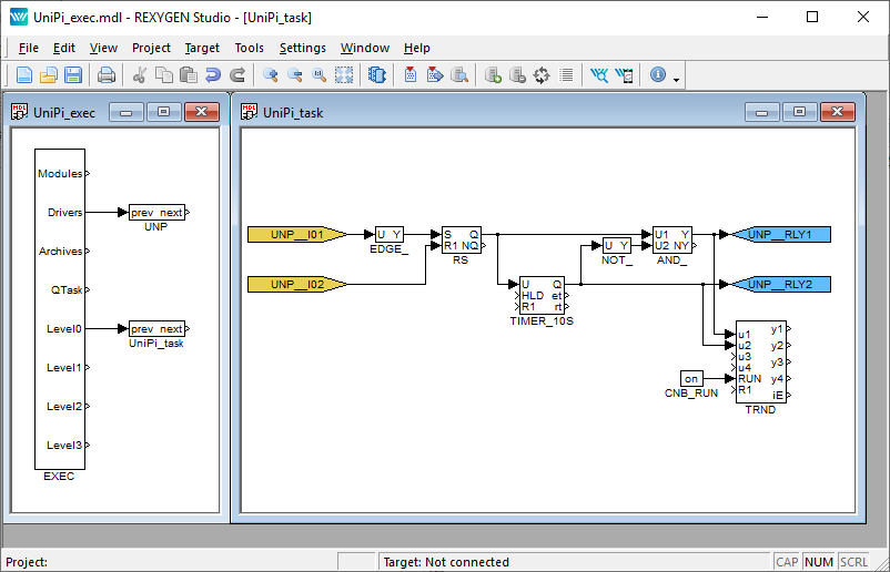
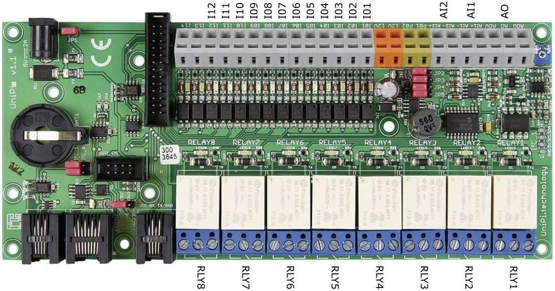
The inputs and outputs of the UniPi v1.1 expansion board can be accessed as shown in Fig. 2.6. The link to a particular IO pin consist of driver name UNP, two underscores __, signal name and number. The numbering of terminals on the UniPi expansion board is shown in Fig. 2.7.
All the input and output flags for the UniPi expansion board are contained in an example project 0122-00_IO_Flags.
2.2.4 Pigeon PLCs
Necessary IODRV block configuration for Pigeon PLCs:
- Block name – PGN
- module – RPiDrv
- classname – PgnDrv
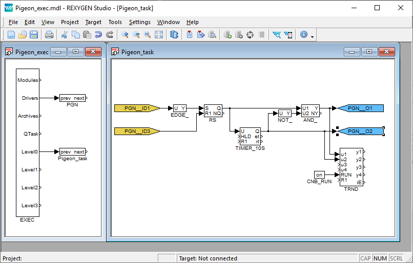
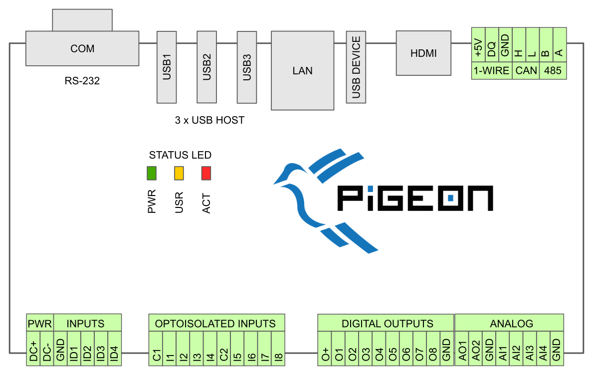
The inputs and outputs of a Pigeon PLC be accessed as shown in Fig. 2.8. The link to a particular IO pin consist of driver name PGN, two underscores __, signal name and number. The numbering of terminals in Pigeon PLCs is shown in Fig. 2.9.
All the input and output flags for Pigeon PLCs are contained in an example project 0123-00_IO_Flags.
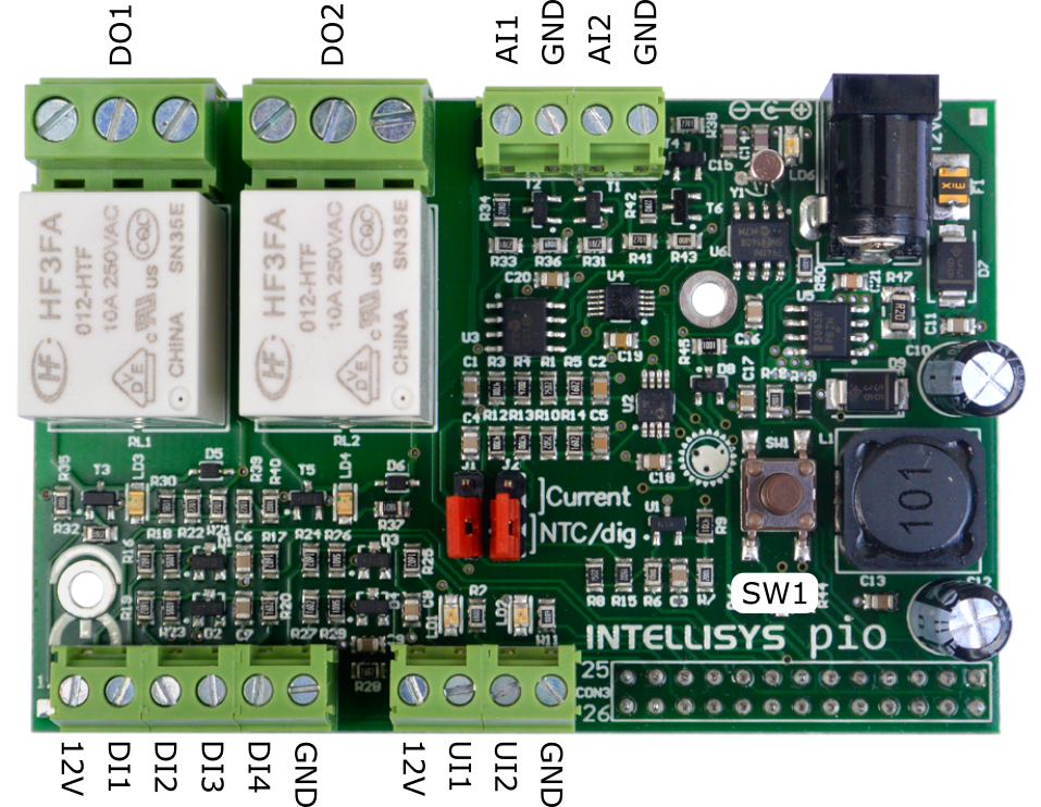
2.2.5 The Intellisys PIO expansion board
Necessary IODRV block configuration for Intellisys PIO expansion board (Obsolete device, no support provided. It is recommended to use the Monarco HAT instead.):
- Block name – PIO
- module – RPiDrv
- classname – PioDrv
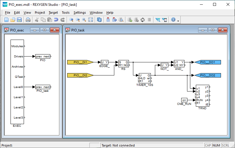
The inputs and outputs of the Intellisys PIO expansion board can be accessed as shown in Fig. 2.10. The link to a particular IO pin consist of driver name PIO, two underscores __, signal name and number. The pin numbering of the Intellisys PIO expansion board is shown in Fig. 2.11.
All the input and output flags for Intellisys PIO expansion board are contained in an example project 0125-00_IO_Flags.
Chapter 3
Troubleshooting
First and foremost, it’s advisable to explore the library of examples, especially the section 0120_Raspberry_Pi, which pertains to the usage of RPiDrv.
In the case that the diagnostic tools of the REXYGEN system report unexpected or incorrect values of inputs or outputs, it is desirable to test the functionality outside the REXYGEN system (command line tools, simple Python script, etc.). Also double check the configuration – the most common problems include:
- Hardware problem – incorrect wiring
- GPIO pin access problem – the GPIO pin is used by other device (SPI bus, I2C bus, serial line) or program
In the case that the given input or output works with other software tools and does not work in the REXYGEN system, report the problem to us, please. E-mail is preferred, reach us at support@rexygen.com. Please include the following information in your description to help us process your request as soon as possible:
- Identification of the REXYGEN system you are using. Simply export it to a file using the REXYGEN Studio program (Target Licensing Export).
- Short and accurate description of your problem.
- The configuration files of the REXYGEN system (.mdl files) reduced to the simplest case which still demonstrates the problematic behavior.
Bibliography
[1] The Raspberry Pi Foundation. Raspberry Pi. http://www.raspberrypi.org, 2013.
[2] Faster CZ s.r.o. Universal Raspberry Pi add-on board. http://www.unipi.technology, 2014.
[3] University of Manchester. PiFace Digital Interface. http://www.piface.org.uk, 2013.
[4] Kristech. Pigeon PLC. http://www.pigeoncomputers.com, 2018.
[5] REX Controls s.r.o.. Getting started with REXYGEN on Raspberry Pi, 2020. .
Documentation reference number: 15831
2023 © REX Controls s.r.o., www.rexygen.com
