EATMT – Extended finite-state automaton
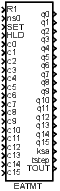
Block SymbolLicensing group: ADVANCED
Function Description
The EATMT block implements a finite automat with at most 256 states and 256 transition rules,
thus it extends the possibilities of the ATMT block.
The current state of the automat , is indicated by individual bits of the integer outputs q0, q1, …, q15. Only a single bit with index of the output is set to 1. The remaining bits of that output and the other outputs are zero. The bits are numbered from zero, least significant bit first. Note that the and operators denote integer division and remainder after integer division respectively. The current state is also indicated by the output.
The transition conditions , ) are activated by individual bits of the inputs c0, c1, …, c15. The k-th transition condition is fulfilled when the -th bit of the input is equal to 1. The transition cannot happen otherwise.
The BMHEXD or BMOCT bitwise multiplexers can be used for composition of the input signals c0, c1, …, c15 from individual Boolean signals. Similarly the output signals q0, q1, …, q15 can be decomposed using the BDHEXD or BDOCT bitwise demultiplexers.
The automat function is defined by the following table of transitions:
| … | ||
Each row of this table represents one transition rule. For example the first row
has the meaning
If
(
is the current state AND transition condition
is fulfilled),
then proceed to the following state
.
The above described meaning of the table row holds for . Negation of the -th transition condition is assumed for .
The above mentioned table can be easily constructed from the automat state diagram or SFC description (Sequential Function Charts, formerly Grafcet).
The input resets the automat to the initial state . The SET input allows manual transition from the current state to the ns0 state when rising edge occurs. The R1 input overpowers the SET input. The input freezes the automat activity, the automat stays in the current state regardless of the c input signals and the tstep timer is not incremented. The TOUT output indicates that the machine remains in the given state longer than expected. The time limits for individual states are defined by the touts array. There is no time limit for the given state when is set to zero. The TOUT output is set to off whenever the automat changes its state.
It is possible to allow more state transitions in one cycle by the morestps parameter. However, this option must be thoroughly considered and tested, namely when the TOUT output is used in transition conditions. In such a case it is strongly recommended to incorporate the ksa output in the transition conditions as well.
The development tools of REXYGEN include also the SFCEditor program. You can create SFC schemes graphically using this tool. Run this editor from REXYGEN Studio by clicking the Configure button in the parameter dialog of the EATMT block.
This block propagates the signal quality. More information can be found in the 1.4 section.
Input
R1 | Block reset | Bool |
ns0 | Target state forced by the SET input | Long (I32) |
SET | Forced transition to state ns0 | Bool |
HLD | Hold | Bool |
c0 | Transition condition | Long (I32) |
c1 | Transition condition | Long (I32) |
c2 | Transition condition | Long (I32) |
c3 | Transition condition | Long (I32) |
c4 | Transition condition | Long (I32) |
c5 | Transition condition | Long (I32) |
c6 | Transition condition | Long (I32) |
c7 | Transition condition | Long (I32) |
c8 | Transition condition | Long (I32) |
c9 | Transition condition | Long (I32) |
c10 | Transition condition | Long (I32) |
c11 | Transition condition | Long (I32) |
c12 | Transition condition | Long (I32) |
c13 | Transition condition | Long (I32) |
c14 | Transition condition | Long (I32) |
c15 | Transition condition | Long (I32) |
Parameter
morestps | Allow multiple transitions in one cycle | Bool |
|
|
|
sfcname | Name of special editor data file | String |
STT | State transition table [0 0 1; 1 1 2; 2 2 3; 3 3 0] | Short (I16) |
touts | Vector of timeouts [1 2 3 4 5 6 7 8 9 10 11 12 13 14 15 16] | Double (F64) |
Output
q0 | Active state indicator | Long (I32) |
q1 | Active state indicator | Long (I32) |
q2 | Active state indicator | Long (I32) |
q3 | Active state indicator | Long (I32) |
q4 | Active state indicator | Long (I32) |
q5 | Active state indicator | Long (I32) |
q6 | Active state indicator | Long (I32) |
q7 | Active state indicator | Long (I32) |
q8 | Active state indicator | Long (I32) |
q9 | Active state indicator | Long (I32) |
q10 | Active state indicator | Long (I32) |
q11 | Active state indicator | Long (I32) |
q12 | Active state indicator | Long (I32) |
q13 | Active state indicator | Long (I32) |
q14 | Active state indicator | Long (I32) |
q15 | Active state indicator | Long (I32) |
ksa | Integer code of the active state | Long (I32) |
tstep | Time elapsed since the last state transition | Double (F64) |
TOUT | Timeout flag | Bool |
[Previous] [Back to top] [Up] [Next]
2024 © REX Controls s.r.o., www.rexygen.com