SAI – Safety analog input
Block SymbolLicensing group: ADVANCED

Function Description
The SAI block tests the input signal u and assesses its validity. The input signal u is considered invalid
(the output )
in the following cases:
- F1: Hardware error. The input signal .
- F2: The input signal u varies too little. The last nc samples of the input u lies within the
interval of width du,
where vmin and vmax are the lower and upper limits of the input u, respectively, and nbits is the number of A/D converter bits. The situation when the input signal u varies too little is shown in the following picture:
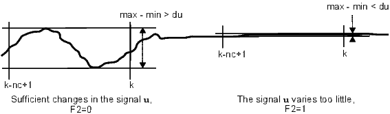
If the parameter nc is set to , the condition F2 is never fulfilled.
- F3: The input signal u varies too much. The last nr samples of the input u filtered by the
SPIKE filter have a span which is greater than rate,
where prate defines the allowed percentage change in the input signal u within the last nr samples (with respect to the overall range of the input signal ). The block includes a SPIKE filter with fixed parameters and suppressing peaks in the input signal to avoid undesirable fulfilling of this condition. See the SPIKE block description for more details. The situation when the input signal u varies too much is shown in the following picture:
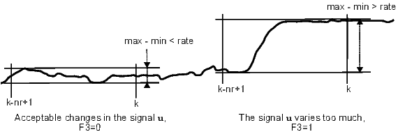
If the parameter nr is set to , the condition F3 is never fulfilled.
- F4: The input signal u is out of range. The last nv samples of the input signal u lie out of the allowed range . If the parameter nv is set to , the condition F4 is never fulfilled.
The signal u is copied to the output y without any modification when it is considered valid. In the other case, the output y is determined by a substitute value from the sv input. In such a case the output E is set to on and the output iE provides the error code. The input R resets the inner error flags F1–F4. For the input R set permanently to on, the invalidity indicator E is set to on for only one cycle period whenever some invalidity condition is fulfilled. On the other hand, for , the output E is set to on and remains true until the reset (rising edge R: offon).
The table of error codes iE resulting from the inner error flags F1–F4:
| F1 | F2 | F3 | F4 | iE |
| 0 | 0 | 0 | 0 | 0 |
| 0 | 0 | 0 | 1 | 1 |
| 0 | 0 | 1 | 0 | 2 |
| 0 | 0 | 1 | 1 | 3 |
| 0 | 1 | 0 | 0 | 4 |
| 0 | 1 | 0 | 1 | 5 |
| 0 | 1 | 1 | 0 | 6 |
| 0 | 1 | 1 | 1 | 7 |
| 1 | * | * | * | 8 |
The nb parameter defines the number of samples which are not included in the validity assessment after initialization of the block (restart). Recommended setting is to allow the SPIKE filter initial conditions to fade away.
This block does not propagates the signal quality. More information can be found in the 1.4 section.
Input
u | Analog input of the block | Double (F64) |
sv | Substitute value for an error case | Double (F64) |
HWF | Hardware error indicator | Bool |
|
|
|
R | Reset inner error flags | Bool |
Parameter
nb | Number of samples to skip at startup 10 | Long (I32) |
nc | Number of samples for invariability testing 10 | Long (I32) |
nbits | Number of A/D converter bits 12 | Long (I32) |
nr | Number of samples for variability testing 10 | Long (I32) |
prate | Maximum allowed percentage change 10.0 | Double (F64) |
nv | Number of samples for out-of-range testing 1 | Long (I32) |
vmin | Lower limit for the input signal -1.0 | Double (F64) |
vmax | Upper limit for the input signal 1.0 | Double (F64) |
Output
y | Analog output of the block | Double (F64) |
yf | Filtered output signal (SPIKE) | Double (F64) |
E | Output signal invalidity indicator | Bool |
|
|
|
iE | Reason of invalidity | Long (I32) |
|
|
|
[Previous] [Back to top] [Up] [Next]
2024 © REX Controls s.r.o., www.rexygen.com