Modbus driver for the REXYGEN system
(the MbDrv module)
User guide
Plzeň (Pilsen), Czech Republic
2024-03-01
Contents
1.1 Introduction
1.2 System requirements
1.3 Installation of the driver on the host computer
1.4 Installation of the driver on the target device
1.4.1 Windows machines
1.4.2 Linux machines
2 Including the driver in the project
2.1 Adding the MbDrv driver
2.2 Connecting the inputs and outputs in the control algorithm
3 I/O driver configuration
3.1 Modbus Master – configuration dialog
3.1.1 Modbus TCP/IP Master configuration
3.1.2 Modbus RTU Master configuration
3.2 Modbus Slave – configuration dialog
3.2.1 Modbus TCP/IP Slave configuration
3.2.2 Modbus RTU Slave configuration
3.3 Modbus items configuration
3.4 Special signals
4 Implementation details
5 Troubleshooting
Chapter 1
The MbDrv driver and the REXYGEN system
1.1 Introduction
This manual describes the MbDrv driver for data exchange between the REXYGEN system and various devices supporting the Modbus protocol [1]. The driver supports both the RTU version for the RS-232 or RS-485 serial lines and the TCP/IP version.
The driver supports both Master and Slave modes. Thus in fact the MbDrv driver contains 4 drivers – serial line Master, serial line Slave, TCP/IP Master and TCP/IP Slave. All versions have much in common and must be installed all at once.
1.2 System requirements
The MbDrv driver can be used on Windows and Linux target devices. The RTU version requires a serial port while the TCP/IP version requires the TCP/IP stack (Ethernet card, USB WiFi dongle etc.).
In order to use the driver, the host computer (development) and the target computer (runtime) must have the following software installed:
|
Host computer |
|
|
Operating system |
one of the following: Windows 10/11, GNU/Linux |
|
Development tools |
version of the REXYGEN system development tools for corresponding operating system |
|
Target device |
|
|
REXYGEN system |
runtime core for the corresponding operating system |
|
IO driver |
version for the corresponding operating system |
|
|
|
|
|
|
1.3 Installation of the driver on the host computer
The MbDrv driver is included in the installation package of the Development tools of the
REXYGEN system. It is necessary to select the corresponding package in the installer. The
REXYGEN system typically installs to the
C:\Program Files\REX Controls\REXYGEN <version> folder.
The following files are copied to the installation folder:
- Bin\MbDrv_H.dll – Configuration part of the MbDrv driver.
- Bin\MbDrv_T.dll – Target part of the MbDrv driver which is called by the RexCore runtime module.
- Doc\PDF\ENGLISH\MbDrv_ENG.pdf – This user manual.
1.4 Installation of the driver on the target device
1.4.1 Windows machines
The target part of the driver, which is used for running REXYGEN Modbus Master or Slave on Windows 10/11 is included in the Development tools of the REXYGEN system as mentioned above.
1.4.2 Linux machines
If there is no RexCore runtime module installed on your target device, install it first using the Getting started guide of the REXYGEN system [2]. The installation encompasses all essential drivers, including MbDrv.
If you wish to install MbDrv separately, you can do so from the command line using the
following command:
Debian:
sudo apt-get install rex-mbdrvt
WAGO:
The MbDrv driver is included in the REXYGEN system image for the WAGO platform and no
action is required.
Chapter 2
Including the driver in the project
The driver is included in the project as soon as the driver is added to the project main file and the inputs and outputs are connected in the control algorithms.
2.1 Adding the MbDrv driver
The project main file with the MbDrv driver included is shown in Figure 2.1. The Modbus Master of the TCP/IP version is shown.
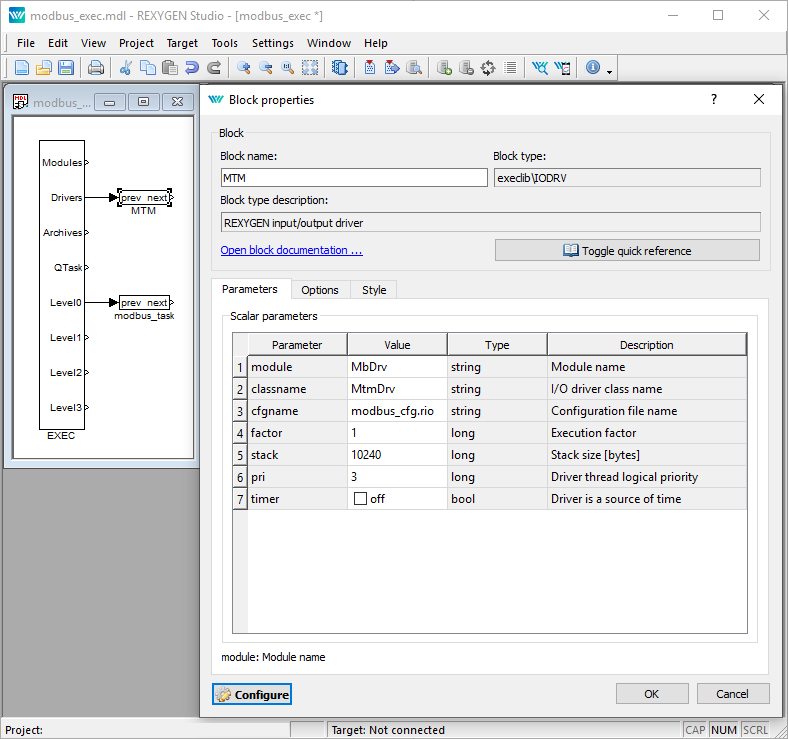
There is one block which must be added to the project to include the driver. A block of type IODRV renamed to MTM and connected to the Drivers output of the main EXEC block. The name of this block (MTM, see Fig. 2.1), is the prefix of all input and output signals provided by this driver. The three most important parameters are:
- module – name of the module linked to the driver, in this case MbDrv – the name is CASE SENSITIVE!
- classname – class of the driver, which defines the role of the target device and the
Modbus version to use:
- MbmDrv – for Modbus RTU Master
- MbsDrv – for Modbus RTUSlave
- MtmDrv – for Modbus TCP/IP Master
- MtsDrv – for Modbus TCP/IP Slave
The name is CASE SENSITIVE!
- cfgname – name of the driver configuration file (*.rio, REXYGEN Input/Output file), which is discussed in chapter 3
The name of this block (MTM, see Fig. 2.1), is the prefix of all input and output signals provided by this driver for Modbus TCP/IP Master. Similarly, the IODRV block can be named MTS, MBM and MBS for TCP/IP Slave, RTU Master and RTU Slave.
The above mentioned parameters of the IODRV function block are configured in the REXYGEN Studio program. The configuration dialog is shown also in Fig. 2.1.
The Configure button opens the configuration dialog of the MbDrv driver, which is described in chapter 3.
2.2 Connecting the inputs and outputs in the control algorithm
The inputs and outputs of the driver must be interconnected with the individual tasks (.mdl files). The individual tasks (QTASK or TASK blocks) are connected to the QTask, Level0,…, Level3 outputs of the main EXEC block. Use the blocks depicted in Fig. 2.2 to interchange data between the control algorithm and the MbDrv driver.
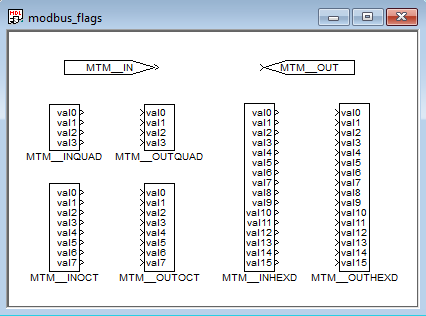
Figure 2.3 shows an example of a PID control loop with one input (temperature) and one output (power) signal provided by the MbDrv driver.
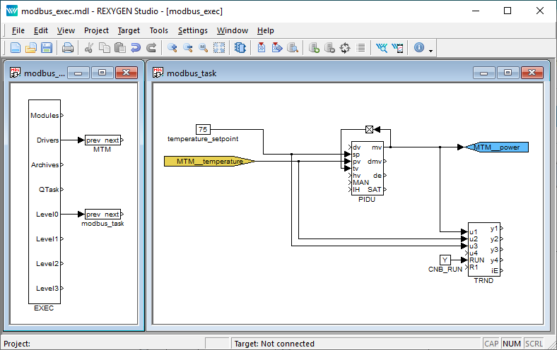
The From block allowing the user to read one input signal has the Goto tag set to MTM__temperature. The Goto block allowing the user to set one output signal has the Goto tag set to MTM__power. The blocks always have the MTM prefix right at the beginning of the tag followed by two __ underscore. The blocks with multiple inputs/outputs have this prefix directly in their name.
The use of multi-input/output blocks is recommended if data exchange rate (sampling frequency) is the priority. See the function block reference manual [3] for details about INOCT, OUTOCT, INHEXD, OUTHEXD blocks.
Example project with input and output flags for the MbDrv driver are prepared by default
in the folder
C:\Program Files\REX Controls\REX <version>\Examples\Modbus_examples\00_IO_Flags.
Chapter 3
I/O driver configuration
This chapter describes the configuration of individual input and output signals and their symbolic naming. The signals are mapped to addresses of the Modbus protocol in individual stations.
The configuration dialog is part of the MbDrv_H.dll file. It can be activated from REXYGEN Studio by pressing the Configure button in the parameters dialog of the IODRV block (see chapter 2).
3.1 Modbus Master – configuration dialog
3.1.1 Modbus TCP/IP Master configuration
The configuration dialog is shown in Figure 3.1.
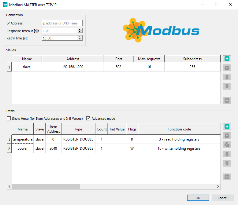
The upper left part of the dialog contains Connection parameters. Namely:
- Response timeout – Maximal time (in seconds) to wait for the response from Slave station. The station is considered malfunctioning if no valid response is received.
- Retry time – Time interval (in seconds) for testing the malfunctioning stations.
- IP Address – Address of the configured Master. To be filled in when more than one Master is running on one device. Otherwise, leave blank. Special value 0.0.0.0 is used for activation of the protocol on all local IP addresses. This field is only available in Advanced mode.
If the REXYGEN system acts as TCP/IP Master, it is necessary to define the Slave stations. The center part of dialog depicted in Fig. 3.1 displays the defined Slave stations. New Slave station can be added by pressing Add slave in the right column. Existing slaves can be edited directly in the Slave list or by pressing Edit slave button.
Following parameters define slave device:
- Name – A unique station name.
- Address – IP address of the Slave station.
- Port – Port (TCP address) of the Slave station. The default port for Modbus is 502.
- Max requests – Maximum number of Modbus telegrams in the queue. Especially the embedded devices with limited memory usually have a small TCP/IP stack buffer. The Master station tracks the requests and responses of each Slave station and postpones the requests if the Slave station fails to respond in a timely manner.
- Subaddress – An extra address field is available with values ranging from 1 to 255. The value 0 is reserved for broadcast purposes, meaning that all subslaves can receive the data, but none should respond. Unless there is a specific reason to do so, it’s advisable not to use the value 0. The value 255 indicates that the slave station does not use subaddressing.
3.1.2 Modbus RTU Master configuration
The configuration dialog is shown in Figure 3.2.
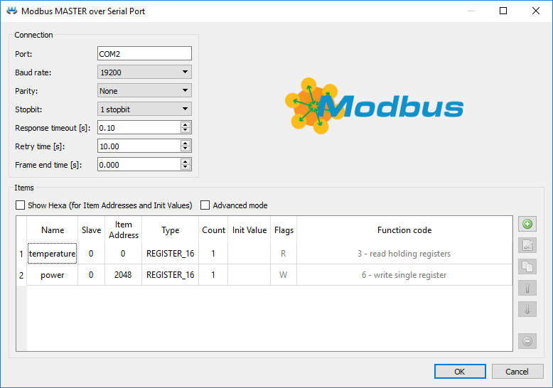
The upper left part of the dialog contains Connection parameters. Namely:
- Port – The serial line used for communication. Usually COM* for Windows target devices or /dev/ttyS* for Linux target devices. Replace "*" symbol according to the chosen serial port! Starting from REXYGEN version 3.0, it is possible to enter virtual ports as well. More information about virtual ports can be found in the Function Blocks Reference manual in the description of the UART block.
- Baud rate – All stations on one bus must use the same baud rate. In bits per second.
- Parity – The error checking mechanism. All stations on one bus must use the same parity.
- Stopbit – Number of stop bits sent at the end of every character. All stations on one bus must use the same value.
- Response timeout – Maximal time (in seconds, default 0.1 s) to wait for the 1st byte of response frame from Slave station after the request was sent out completely. The station is considered malfunctioning if no valid response is received 3 times in a row. Do not use long timeouts, especially when there are multiple Slave stations on the bus. In case of a malfunctioning station it is not possible to communicate with other stations for the whole timeout period.
- Retry time – Time interval (in seconds, default 10 s) to wait before retrying communication with malfunctioning stations.
- Frame end time – How long silence time on the line is considered as the frame end. Value 0 means automatic configuration based on baud rate according to Modbus specification (3.5 characters) with some safety margin for processing in the operating system. Please try to increase this value up to the value of Response timeout parameter if you are facing Read serial device timed out errors in system log.
3.2 Modbus Slave – configuration dialog
3.2.1 Modbus TCP/IP Slave configuration
The configuration dialog is shown in Figure 3.3.
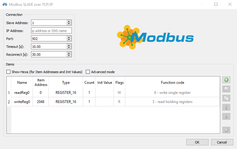
The upper left part of the dialog contains Connection parameters. Namely:
- Slave address – Slave device address. There can be up to 254 Slave stations on same IP address. The address 0 is reserved for broadcast and must not be used. The address 255 indicates that the subaddress is ignored.
- IP Address – Defines the network adapter where the Slave is listening. Leave it blank or set it to value 0.0.0.0 for all network adapters or specify IP Address of a chosen one.
- Port – Port (TCP address) of the Slave station. The default port for Modbus is 502.
3.2.2 Modbus RTU Slave configuration
The configuration dialog is shown in Figure 3.4.
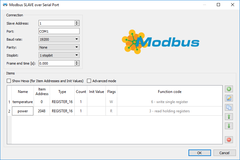
The upper left part of the dialog contains Connection parameters. Namely:
- Slave address – To specify a slave device, its address must be determined. Up to 254 Slave stations can be connected, but without a repeater, only up to 32 stations can be accommodated. The address 0 is reserved for broadcasting and should not be used. In the TCP version, the address 255 has a specific meaning and should be avoided.
- Port – The serial line used for communication. Usually COM* for Windows target devices or /dev/ttyS* for Linux target devices. Replace "*" symbol according to the chosen serial port! Starting from REXYGEN version 3.0, it is possible to enter virtual ports as well. More information about virtual ports can be found in the Function Blocks Reference manual in the description of the UART block.
- Baud rate – All stations on one bus must use the same baud rate. In bits per second.
- Parity – The error checking mechanism. All stations on one bus must use the same parity.
- Stopbit – Number of stop bits sent at the end of every character. All stations on one bus must use the same value.
- Frame end time – How long silence time on the line is considered as the frame end. Value 0 means automatic configuration based on baud rate according to Modbus specification (3.5 characters) with some safety margin for processing in the operating system. Please try to increase this value up to the value of Response timeout parameter if you are facing Read serial device timed out errors in system log.
3.3 Modbus items configuration
The configuration dialog is shown in Figure 3.5.
The lower part of the configuration dialog displays the configured signals. Each line has a symbolic name and corresponds to one signal or a group of signals. New item can be added by pressing the Add item button in the right column of the configuration dialog. The item can be similarly edited by pressing the Edit item button. Some of the parameters (Name, Item Address, Type and Count) can be edited directly in the Item list. If you choose Advanced mode it unlocks all other parameters for direct edit in the Item list.
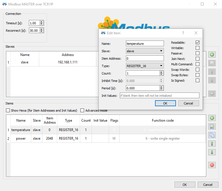
The individual columns have the following meaning:
- Name – A unique signal name.
- Slave – Select slave device. Available only in Modbus TCP/IP Master item configuration.
- Slave Address – Slave device address. Available only for Modbus RTU Master item configuration.
- Item Address – Address of the object in the device. All objects (values) within one station have an identification number (address) from the range 0 to 65535.
- Type – Signal type. The names respect the Modbus specification:
Input Digital input Coil Digital output InReg 16 16-bit integer number 0…65535 or -32768…32767 (depend on Is Signed flag), InReg 32 32-bit integer number 0…4294967296 or -2147483648…2147483647 (depend on Is Signed flag), InReg 64 64-bit integer number -9223372036854775808…9223372036854775807 (unsigned is not supported), InReg float 4-byte floating point number (Is Signed flag is ignored), InReg double 8-byte floating point number (Is Signed flag is ignored), Register 16 16-bit integer number 0…65535 or -32768…32767 (depend on Is Signed flag), Register 32 32-bit integer number 0…4294967296 or -2147483648…2147483647 (depend on Is Signed flag), Register 64 64-bit integer number -9223372036854775808…9223372036854775807 (unsigned is not supported), Register float 4-byte floating point number (Is Signed flag is ignored), Register double 8-byte floating point number (Is Signed flag is ignored), Register string text variable (Count is number of bytes occupied by text in this case) Note: REGISTER is called Holding Register and INREG is called Input Register by some vendors.
- Count – Number of values. One item can represent a group of values which are read at once using the multi-input/output block. This number defines how many values to read. The number does not necessarily correlate with the number of inputs/outputs of the block. In such a case, the unused pins are not updated.
- Inhibit Time – Valid only for Writable (W) items. Defines the minimum length of time that must be allowed to elapse between the transmissions of the item.
- Period – Refresh period in seconds. Nonzero values define the period, zero respects the period given by the corresponding IODRV block.
- Initial value – The initial value to set the signal to when initializing the driver. Use square brackets for groups of values. Separate the values by spaces.
- Readable (R) – Tick this checkbox to allow reading of the value in the REXYGEN algorithm. In Slave configuration, such items will be writable for the Master.
- Writable (W) – Tick this checkbox to allow writing of the value from the REXYGEN algorithm. In Slave configuration, such items will be readable for the Master.
- Passive (P) – In some cases it is more efficient to transmit a large group of signals at once (maximum is 125 values). But we still want to work with individual signals or less populated groups in the algorithm. In that case we define one big array and a number of small groups overlaying the data registers. Only the big array is active, the other signals are set to passive. This field is available only in the Master configuration.
- Join next (J) – Tick this checkbox to use the read-write command of the Modbus specification. The readable signal is joined with its successor (the writable item one line below) and the data is exchanged using a single command. This field is available only in the Master configuration.
- Multi command (m) – Tick this checkbox to force multi-read or multi-write command even if only one value is transmitted. Useful for Modbus stations supporting only a subset of Modbus commands. This field is available only in the Master configuration.
- Swap word (a) – 32-bit numbers are represented by 2 successive 16-bit numbers in Modbus. This flag defines the order of lower and upper word. The same holds for real numbers as they are represented by 2 or 4 successive 16-bit registers.
- Swap byte (b) – The upper byte of the 16-bit number is transmitted first in Modbus (the so-called big-endian format). However, some devices use little-endian implementation. This flag becomes handy in such a case.
- Is Signed (S) – Tick this checkbox to treat the integer number as a signed number.
- As Array (V) – The values are transmitted to the REXYGEN algorithm in the form of an array. If multiple values are involved, a From block is utilized to connect the array signal from the driver, along with one or more VTOR blocks.
3.4 Special signals
Additional diagnostic signals and attributes are available, namely:
| ErrorFrame | number of invalid frames received |
| ErrorTimeout | number of timeout occurrences |
| ErrorData | number of valid frames with unexpected data or error code |
| ErrorReset | flag for resetting the above mentioned counters |
| ComName | configuration parameter Port (serial master and serial slave only) |
| BaudRate | configuration parameter BaudRate (serial only) |
| Parity | configuration parameter Parity (serial only) |
| SpaceTime | additional delay between sending packets in milliseconds (serial master only) |
| SyncTime | additional timeout between received bytes in telegram (serial only) |
| Timeout | configuration parameter Response timeout, but in milliseconds |
| Gap | configuration parameter Retry time, but in milliseconds |
| Browse | non-zero values switch driver into browsing address space mode. Output is in system log. |
Every signal also has its attributes, namely:
| _Value | alias for signal value |
| _ReadEnable | configuration parameter Readable |
| _RE | same as _ReadEnable |
| _WriteEnable | configuration parameter Writable |
| _WE | same as _WriteEnable |
| _Address | configuration parameter Item address |
| _Slave | configuration parameter Slave address |
| _Fresh | time elapsed since the last data update (in seconds) |
| _Period | configuration parameter Period |
| _Send | flag indicating that the value is waiting to be stored in the Slave device. Force write to slave if used as output and attribute value is not zero. |
| _WF | same as _Send |
The Fresh attribute is read-only, the other attributes are both readable and writable. Beware the Fresh attribute is updated even if the read/write operation fails. In such a case the signal quality is set to BAD or UNCERTAIN.
Thus if we want to know the freshness of the MBM__IN signal, we use the From block and set the Goto Tag parameter to MBM__IN_Fresh.
In addition, there are other signals that represent the state and attributes of the Slave device. All this suffix are prefixed by driver and slave name (e.g. MTM__SlaveName ). The following are the available suffixes:
| _Connected | Connection to the slave is established. Force connect or disconnect if used as output. |
| _Connecting | Connection request sent or connection established. |
| _Status | More detailed connection status. Internal debugging only. |
| _Address | configuration parameter Address |
| _Port | configuration parameter Port |
| _SubAddr | configuration parameter Subaddress |
Chapter 4
Implementation details
Additional information about Modbus implementation in the REXYGEN system is gathered in this chapter.
- Do not change the SyncTime parameter unless necessary (default setting: 0). Only minor devices with slow CPU detect the packets incorrectly and need longer time between them.
- The Timeout period is measured from the end of the request to the end of the response. The time necessary to send the Modbus message is added to the timeout. Modbus message contains 10 to 16 bytes plus the values to transmit. Maximal length is 256 bytes.
- The Reconnect parameter is important only if there are multiple stations on one bus.
- The Modbus protocol uses only 16-bit registers or groups of successive 16-bit registers. The REGISTER_32 and REGISTER_FLOAT thus occupy two 16-bit registers. If we use the address 100 for REGISTER_FLOAT, we cannot use the address 101 as it is already occupied by the float register.
- It is recommended not to combine read and write operations on one signal. Use two strictly read-only and write-only signals pointing to the same register if you need both reading and writing the data.
- The Readable and Writable flags are always relative to the REXYGEN control algorithm running on the REXYGEN target device. It is intuitive for Modbus Master but it might be confusing for the Slave. The Modbus Master writes to the registers, which are configured as readable in the Slave.
- Only the address of the first item should be used when defining groups of signals ().
- The Period cannot be faster than reading and writing all signals. Use this parameter to avoid repetitive transmission of slowly changing signals and save the bandwidth for other signals. The real period can be displayed in the Diagnostics section of the REXYGEN Studio program.
- The values are read/written in the same order as they are shown in the configuration dialog.
- Some Modbus configuration tools use register addresses starting from 40001 (or from 400001 in the case of 984-series devices) for holding registers. The REXYGEN system always uses the physical addresses starting from 0.
- The Modbus communication is asynchronous to the REXYGEN control algorithm. The driver contains a cache for all signals. The Modbus Master cycles through all signals. If the signal is blocked by the Period parameter or the corresponding station is not responding, the signal is skipped. Otherwise the read query or write command is issued. If there is no response within the timeout period, the Master marks the corresponding station as Disconnected. The Modbus Slave only waits for requests of the Master and returns the cached values or updates the cache. All possible situations are described in the following table:
- If the checkox SwapWord is not checked, word
order is big-endian for REGISTER_32, INREG_32 and little-endian (more exactly
host-endian) for REGISTER_FLOAT, REGISTER_64, REGISTER_DOUBLE,
INREG_FLOAT, INREG_64, INREG_DOUBLE. The checkbox SwapWord is
ignored for other types. Byte order is big-endian if the checkbox SwapByte is not
checked. It is usually not critical - try default and if value is read but different,
check register and slave id and then try SwapByte or/and SwapWord.
Master
Slave
read
reads the cached value (obtained in the previous cycle of the Modbus line)
reads the cached value (updated by the last write command on the Modbus line)
write
writes the value to cache (if it differs from the previous value, it is transmitted during the nearest Modbus cycle)
writes the value to the cache (Modbus Master receives the value as soon as it issues the read command)
read and write
cached value is read, standard write operation follows
cached value is read, standard write operation follows
Chapter 5
Troubleshooting
!!!WARNING!!! Up to version 2.51.0.13636 reading type REGISTER32 has oposite word order for pasive item and active item. The problem is fixed in version 2.51.0.13637 and higher. So all project created in version 2.51.0.13636 or older are converted into version 2.51.0.13637 or newer must be checked and all item of the type REGISTER32 with Passive flag checked must be Swap word flag toggled.
First and foremost, it’s advisable to explore the library of examples, especially the sections 0401_Modbus_RTU and 0402_Modbus_TCP, which pertain to the usage of MbDrv.
In the case that the diagnostic tools of the REXYGEN system (e.g. Watch mode in the REXYGEN Studio) report unexpected or incorrect values of inputs or outputs, it is desirable to test the functionality outside the REXYGEN system (command line tools, Modbus simulators, etc.). Also double check the configuration – the most common problems include:
- Hardware problem – incorrect wiring (cross-cable vs. direct-cable, connector pinout), TTL vs. RS232 signal levels, signal polarity, etc.
- The configured serial channel is occupied by another program.
- The device uses non-standard Modbus implementation (byte-order or word-order).
- The device is very slow and needs longer SyncTime.
- Incorrect Slave address or register number.
- Mismatch in readable and writable flags.
- The signal is defined in inappropriate configuration file (when using multiple Modbus lines).
- Parameters may be modified from algorithm. Check the values, especially during startup phase.
- ADAM 5000 TCP (and possibly other devices) does not work correctly if TCP
stack combines two or more Modbus messages into one Ethernet frame. Messages
indicating that timeout expired appear in the system log. A workaround is
to set Max. requests = 1 for that particular slave device, however it reduces
communication throughput and response times.
Setting Max. requests = 1 is recommended whenever an unexpected behavior of the Modbus communication is observed.
- float and double number must be according IEEE 754 specification (binary32 and binary64 respectively). Some PLC use different coding that could not be used.
In the case that the given input or output works with other software tools and does not work in the REXYGEN system, report the problem to us, please. E-mail is preferred, reach us at support@rexygen.com. Please include the following information in your description to help us process your request as soon as possible:
- Identification of the REXYGEN system you are using. Simply export it to a file using the REXYGEN Studio program (Target Licence Export).
- Short and accurate description of your problem.
- The configuration files of the REXYGEN system (.mdl and .rio files) reduced to the simplest case which still demonstrates the problematic behavior.
Bibliography
[1] Modbus Application Protocol Specification V1.1b. http://www.Modbus-IDA.org, 2006.
[2] REX Controls s.r.o.. Getting started with REXYGEN on Debian, 2020. .
[3] REX Controls s.r.o.. Function blocks of REXYGEN – reference manual, 2020. .
Documentation reference number: 16076
2024 © REX Controls s.r.o., www.rexygen.com