REXYGEN system SimDrv driver
User guide
Plzeň (Pilsen), Czech Republic
2024-03-01
Contents
1.1 Introduction
1.2 System requirements
1.3 Installation of the driver on the development computer
1.4 Installation of the driver on a target device
1.4.1 Devices with Windows operating system
1.4.2 Devices with Linux operating system
2 Including the Driver in the Application Project
2.1 Adding the SimDrv Driver to the Project
2.2 Connecting the inputs and outputs to the control algorithm
3 Driver Configuration
3.1 Configuration Dialog Window
3.1.1 Displaying Configured Signals
3.1.2 Configuration of Inputs and Outputs
4 Implementation Details
5 Troubleshooting
Chapter 1
The SimDrv driver and the REXYGEN system
1.1 Introduction
This manual describes the use of the SimDrv driver to facilitate algorithm debugging of the REXYGEN system on a non-target platform (usually a personal computer). The driver cannot simulate the entire technology but allows generating various periodic signals and a signal based on another value. The concept of the simulation driver enables a very quick creation of a simulation driver configuration (.rio file) for an existing scheme (.mdl file) with references to any REXYGEN system driver. When it is necessary to replace SimDrv with a real driver, the project remains almost unchanged, only in the main EXEC block, SimDrv will be replaced by another driver with the same name. The SimDrv driver was developed by the REX Controls company.
1.2 System requirements
The SimDrv driver can be operated on all platforms and systems where the full-fledged REXYGEN control system can be operated.
It is assumed that the development (configuration) computer is the target device itself. However, this is not necessary. For the driver to be usable, the following software equipment must be installed on the development computer and the target device:
|
Development computer |
|
|
Operating system |
one of the systems: Windows 10/11, GNU/Linux |
|
Development tools |
REXYGEN version for the given operating system |
|
Target device |
|
|
REXYGEN control system |
core for the corresponding operating system |
|
I/O driver |
version for the corresponding operating system |
|
|
|
|
|
|
In the case that the development computer is directly the target device, only one copy of the REXYGEN control system is installed.
1.3 Installation of the driver on the development computer
The SimDrv driver is installed as part of the REXYGEN system installation. It is included in the installer of the development tools for the REXYGEN system and it is necessary to select it during the installation process. During a typical installation, the REXYGEN control system is installed in the target directory C:\ProgramFiles\REXControls\REXYGEN<version>.
After a successful installation, the following files are copied to the target directory:
- Bin\SimDrv_H.dll – Configuration part of the SimDrv driver.
- Bin\SimDrv_T.dll – Target part of the SimDrv driver run by the RexCore executive. This version is used if the target device runs the Windows 10/11 operating system. For other target platforms, the corresponding version of the REXYGEN system must be installed.
- DOC\PDF\ENGLISH\SimDrv_ENG.pdf This user manual.
1.4 Installation of the driver on a target device
1.4.1 Devices with Windows operating system
The target part of the driver, used for REXYGEN on Windows 10/11, is included within the REXYGEN development tools.
1.4.2 Devices with Linux operating system
If you do not already have the RexCore runtime module of the REXYGEN control system installed, install it first according to the "Getting started with REXYGEN" guide [1]. The installation includes all necessary drivers, including SimDrv.
If you want to install SimDrv separately, you can do so from the command prompt using the command:
sudo apt-get install rex-simdrvt
Chapter 2
Including the Driver in the Application Project
Including the driver in the application project involves adding the driver to the main project file and connecting the driver’s inputs and outputs in the control algorithms.
2.1 Adding the SimDrv Driver to the Project
The addition of the SimDrv driver to the main project file is illustrated in Fig. 2.1. The philosophy of using SimDrv is such that the driver should replace another, specific driver.
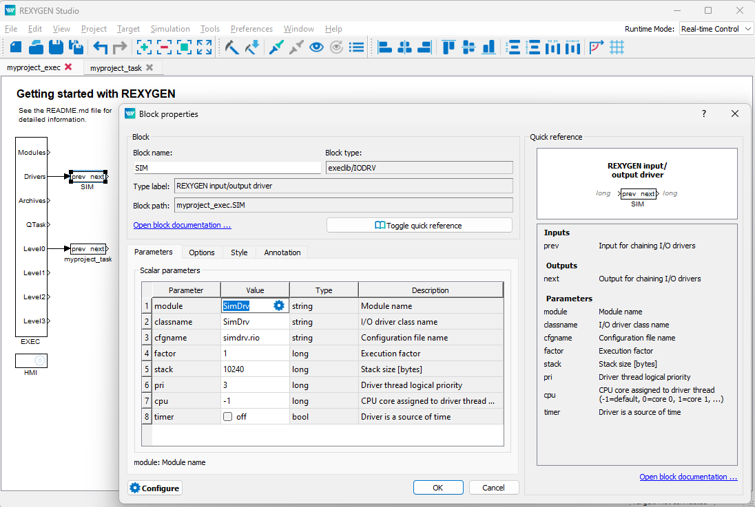
To integrate the driver into the project, the IODRV block is used, which is connected to the Drivers output of the main EXEC block. The SimDrv driver is a special type of driver as it serves to temporarily replace a real driver. The standard convention for naming drivers tells us that the driver should be named after its type. In this specific case, we should thus name the driver SIM (see Figure 2.1). However, the name of the driver also determines the names of all its input and output signals. If we were to name the SimDrv driver SIM, we would have to modify the names of all its input and output signals when exchanging the driver. Therefore, it is advisable to name the SimDrv driver to match the name of the replaced driver, for example, MNR, RPi, WG, etc. The four most important parameters of the IODRV block are:
- module – the name of the module in which the driver is implemented, in this case, SimDrv
- classname – the driver class, in this case, SimDrv
- cfgname – the name of the driver configuration file. The creation of the configuration file is described in chapter 3. It is recommended to enter it in the form <class_name>.rio, where the extension *.rio (REXYGEN Input/Output) has been introduced for this purpose.
- factor – a multiple of the tick parameter of the EXEC block defining the period for executing driver tasks.
ATTENTION! The parameter settings are case sensitive!
The parameters of the IODRV block just described are configured in the program REXYGEN Studio in the dialog box, which is also shown in Figure 2.1.
The Configure button opens the configuration dialog for the SimDrv driver, which is described in chapter 3.
2.2 Connecting the inputs and outputs to the control algorithm
Inputs and outputs from drivers can be attached to the algorithm in individual tasks using several functional blocks:
- For reading a single value, it is advantageous to use the From block.
- For writing a single value, the Goto block is used.
- As the driver allows obtaining several inputs or setting several outputs under one symbolic name, it is advantageous to use blocks for quadruple, octuple, and sixteenfold inputs and outputs (INQUAD, OUTQUAD, INOCT, OUTOCT, and INHEXD, OUTHEXD). The advantage of such use is to increase the speed and partly the clarity of algorithms.
A detailed description of the blocks can be found in the manual [2].
In the main project file, the tasks are listed only by reference in blocks of type QTASK or TASK connected to outputs QTask, Level0, ... , Level3 of the executive. The input and output blocks should be taken from the manual for the driver, which will then replace SimDrv, for example, from manuals for the Monarco, Raspberry, Wago, etc., drivers.
The affiliation of the From and Goto blocks to a given driver is given by their parameter Goto tag, which starts with the name of this driver (see fig.2.1), continues with the delimiter __ (two underscore characters in a row) and ends with the name of the signal defined in the driver configuration (see chapter3). For the INQUAD, OUTQUAD, INOCT, OUTOCT, and INHEXD, OUTHEXD blocks, this identification string is entered directly into their name. For a specific example, consult the manual of the driver that will replace SimDrv.
Chapter 3
Driver Configuration
In this chapter, the configuration of individual input and output signals and their symbolic naming is described. Signals are mapped to individual values provided by the simulation SimDrv.
3.1 Configuration Dialog Window
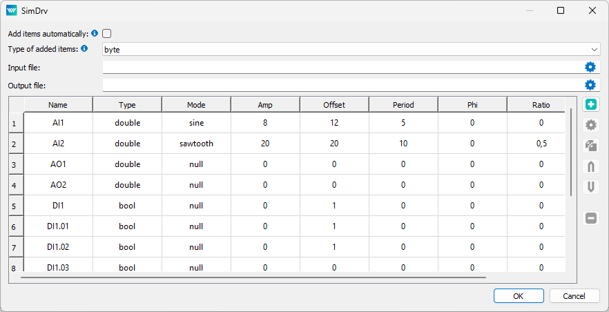
The configuration dialog window depicted in Fig. 3.1 is part of the SimDrv_H.dll file. It can be activated via the REXYGEN Studio program by clicking on the Configure button in the IODRV block parameter dialog window (see Chapter 2) or by clicking on the gear icon located on the right side of the IODRV block.
At the top of the dialog are several objects of global significance:
- Add items automatically – If checked, when compiling with REXYGEN Compiler, all references to I/O blocks from all connected tasks that are not yet in the configuration will be automatically added. If unchecked, items will be used only for compilation by REXYGEN Compiler to avoid compile errors, but will not be added to the configuration file.
- Type of added items – The type of items that will be automatically added. If Unknown is selected, the item will not be added and an error will be reported during compilation.
- Input file – CSV file with values for inputs. Can be used instead of Mode at the bottom of the configuration window.
- Output file – CSV file where output values will be saved.
In the bottom part of the window, individual signals are defined which can then be used to simulate reading or writing in the REXYGEN control system. Simply add signals, or have them automatically generated at compilation by checking the Add Items automatically option.
Signals can be added to the table by pressing the Add item button, edited with the Edit item button, or by double-clicking on an item in the table. See Fig. 3.1.
3.1.1 Displaying Configured Signals
In the middle part of the dialog window, the configured signals are displayed in a tabular format. Each row corresponds to a signal with an assigned symbolic name. The columns of the table have the same meaning as the input fields during configuration and are described in Section 3.1.2.
3.1.2 Configuration of Inputs and Outputs
The other elements of the dialog (i.e., the input fields at the bottom) from Fig. 3.1 are used for the configuration of input and output signals. These are the fields:
- Name – The name of the signal in the REXYGEN system. It must be entered uniquely.
- Type – The type of signal. The significance is evident. It is recommended to use the following types:
Bool boolean signal, Long integer (32 bits signed, i.e., -2147483648 …2147483647) Double floating-point number (64-bit range) - Mode – The mode for signal generation. For outputs (i.e., signals from the .mdl drawing to the driver), it must be Null. For inputs, there are several generators, with the generator’s value multiplied by the Amplitude parameter and the Offset parameter’s value added to the result, i.e., . For periodic generators, the start of generation is shifted by the value given by the Phase parameter. The following modes generate:
Null a constant value determined by the Offset parameter, Noise a pseudo-random number in the range , Rectangle a rectangular pattern – alternating values of 1 for and -1 for the remainder of the period, Sawtooth a triangular pattern – value with linear increase for and linear decrease for the rest of the period, Sin function , Filter 1st order filter from the signal, whose number is in the Period parameter, i.e., , - Amplitude – The amplitude of the generated signal.
- Offset – The offset of the generated signal (added to the value).
- Period – The period of the generator in seconds.
- Phase – The relative shift of the generator’s start in time; it can take values .
- Ratio – The proportion of the first part of the period for the types Sawtooth and Rectangle; it can take values .
Chapter 4
Implementation Details
This chapter gathers insights that have arisen from previous experiences. Certain configuration items are often misunderstood, and a detailed description earlier would worsen the readability of the text. Therefore, these insights are provided in a separate chapter. The method of value transfer is also described in detail here.
The driver is typically used when the target platform is not available. In all blocks in IODRV in exec.mdl, we change the module and classname parameters to SimDrv and set a different configuration file name (the cfgname parameter). Then we press the Configure button (if the configuration file does not exist - we opt to create a new one) and set Type of added items to long (other types can be used, but long implicitly converts to bool and double, and other types are rare) and select Add items automatically and save with the OK button. Then we compile the project (in REXYGEN Studio go to Project|Compile). Now we can run exec.rex, but all inputs will have a value of 0. It is now possible to rerun the configuration of the simulation driver (button Configure) and set more suitable generators or value types for the inputs depending on the technology’s nature.
Chapter 5
Troubleshooting
In the event that the SimDrv driver functions correctly in simple test cases but does not work with the necessary configuration, please send information about the issue by email to support@rexcontrols.com. For the quickest resolution of the problem, the information should include:
- Identification details of your installation exported using the REXYGEN Studio program (Target Licensing Export).
- A brief and clear description of the problem.
- The most simplified configuration of the REXYGENcontrol system in which the problem occurs (in the file format with the extension .mdl).
- The SimDrv driver configuration file.
Bibliography
[1] REX Controls s.r.o.. Getting started with REXYGEN on Debian, 2020. .
[2] REX Controls s.r.o.. Function blocks of REXYGEN – reference manual, 2020. .
Documentation reference number: 16076
2024 © REX Controls s.r.o., www.rexygen.com