I/O Configuration of Target Platforms
User guide
2025-03-27
Plzeň (Pilsen), Czech Republic
Contents
2 Physical connections
2.1 WAGO PFC100/200
2.2 Raspberry Pi
2.3 Monarco HAT
2.4 REX M527, Unipi Patron/Axon/Neuron
2.5 Weidmüller u-OS PLC (WL2000, M3000, M4000)
3 Adding inputs and outputs to the project
4 Working with I/O Signals
4.1 General steps for all platforms
4.2 Specific parameters for individual platforms
4.2.1 WAGO PFC100/200
4.2.2 Raspberry Pi
4.2.3 Monarco HAT
4.2.4 REX M527, Unipi Patron/Axon/Neuron
4.2.5 Weidmüller u-OS PLC (WL2000, M3000, M4000)
5 Interacting with the algorithm
6 Updating the HMI
7 Examples
8 Next Steps
Chapter 1
Introduction
To demonstrate the configuration of inputs and outputs on different platforms, we will use the project created in the user guide [1] and continue with it. So far, the algorithm has not interacted with the outside world; it has not been connected to any physical signal or external data. Now, we will use the platform’s input and output signals to interact with the real world. For the Raspberry Pi, we will use GPIO pins, which can be configured as inputs or outputs.
Two physical switches will be used as inputs, and a software timer will control one output signal. In other words, this guide is dedicated to transitioning from the general example 0101-01 to the default project for each platform shown in [2].
Chapter 2
Physical connections
This part of the procedure is individual for each target device. Go to the section dedicated to your platform and continue with Chapter 3 after wiring.
2.1 WAGO PFC100/200
For this example project a simple setup is assumed:
- 1x 750-8102 PFC100 or 750-8202 PFC200 controller with power supply
- 1x 750-430 module (8 digital inputs)
- 1x 750-603 module (24V potential distribution)
- 1x 750-530 module (8 digital outputs)
- 1x 750-604 module (0V potential distribution)
- 1x 750-600 mandatory end module
Connect the switches and an external relay as shown below. The relay is optional, as the output status is also indicated by the onboard LED of the module.
IMPORTANT: Note that numbering of the terminals on the WAGO modules (above) does not comply with channel numbering (below)! Always follow the DI1..8, DO1..8, AI1..4, etc. notation as per WAGO documentation.
For details and wiring examples for the platform refer to documentation of the WAGO 750/753 modular I/O system.
2.2 Raspberry Pi
Connect the switches, protective resistors (330 Ohm) and a LED indicator as shown below.
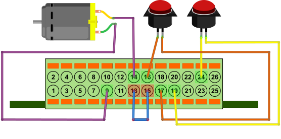
2.3 Monarco HAT
Connect the switches as shown below. The motor is optional, as the output status is also indicated by the onboard LED.
2.4 REX M527, Unipi Patron/Axon/Neuron
Connect the switches as shown below. The motor is optional, as the output status is also indicated by the onboard LED.
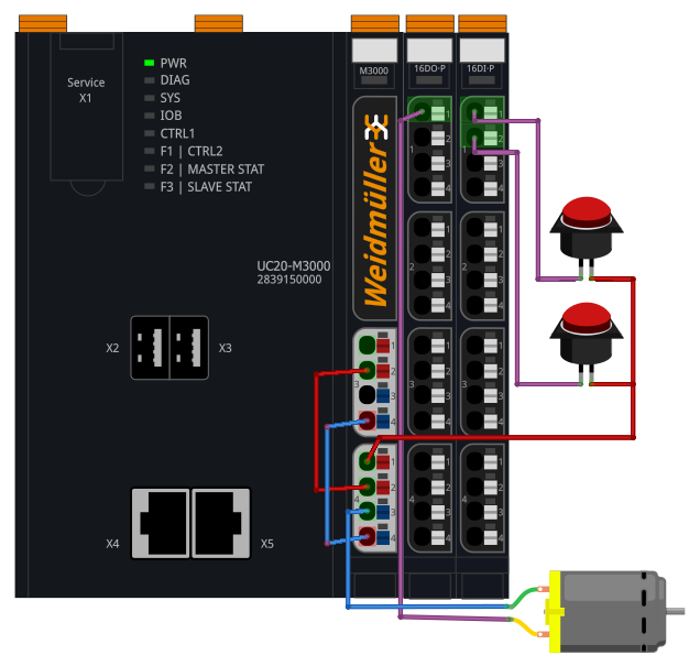
2.5 Weidmüller u-OS PLC (WL2000, M3000, M4000)
Connect the switches as shown below. The motor is optional, as the output status is also indicated by the onboard LED.
Chapter 3
Adding inputs and outputs to the project
Now when we have everything wired up, it’s time to include the physical signals into the algorithm. You need to expand your project main file with an additional function block to access the inputs and outputs from the control algorithm in your project. Insert the EXEC/IODRV blocks from the Block library and attach it to the EXEC block as shown below.
In the task file, delete the CNB_SWITCH1 and CNB_SWITCH3 blocks and replace them with INOUT/From blocks. These will be the input signals. Also add one INOUT/Goto block, which will serve as an output and which will be controlled by the timer. Remember that a new branch of the line is created by dragging with the right mouse button.
Chapter 4
Working with I/O Signals
Now we tell the compiler to use a specific I/O driver. To do this, edit the IODRV block parameters according to the following steps:
4.1 General steps for all platforms
- Set the IODRV block to communicate with the appropriate module for the target platform
by modifying the block parameters:
- module=<module name>
- classname=<class name>
- cfgname – set as needed (see below).
- factor=1
- Leave the other parameters intact.
- Rename the IODRV block as recommended for each platform (e.g. WG for WAGO, GPIO for Raspberry Pi, etc.). This name will also serve as a prefix for all I/O signals of this driver.
- If necessary, create the configuration file for the I/O driver. Click the Configure button and fill in the form as shown below. After that, click OK and the file will be stored in the project folder.
- In the From and Goto blocks, set the GotoTag parameter to the appropriate I/O signal. The GotoTag parameter must be in the format <prefix>__<signal name>, where the prefix is the name of the IODRV block. Note the double underscore characters. For example, WG__S1M430C1 for channel 1 of the 750-430 module in memory slot 1.
At the end of this Chapter, your project should look like the image below with the IODRV block name and signal prefixes matching the platform you are using.
4.2 Specific parameters for individual platforms
4.2.1 WAGO PFC100/200
- module=WagoDrv
- classname=WagoDrv
- cfgname – leave blank
- Recommended name IODRV and signals prefix: WG
For the needs of the project, set the GotoTag parameters for the From blocks as:
- WG__S1M430C1 – The first physical switch is connected to channel 1 (DI1) of the 750-430 module, which is in memory slot 1.
- WG__S1M430C3 – The second physical switch is connected to channel 3 of the same module.
Channel 1 of the 750-530 module in memory slot 2 will serve as control signal for the external relay. Set the Goto block (GotoTag = WG__S2M530C1).
IMPORTANT: Potential distribution modules do not provide any data, therefore they do not take up any memory and are not counted in the module slot numbering!
Similarly for other I/Os we could use the following flags:
- Goto, WG__S2M530C8 – channel 8 of the 750-530 module in slot 2
- From, WG__S3M555C2 – channel 2 of the 750-555 module in slot 3 (not present in this example)
- etc.
A detailed description of the I/O driver for WAGO PFC100/200 is available in a separate manual [3].
4.2.2 Raspberry Pi
- module=GpioDrv
- classname=GpioDrv
- cfgname=gpio.rio
- Recommended name IODRV and signals prefix: GPIO
Remember to click the Configure button. This will create a default I/O driver configuration file (.rio). For Raspberry Pi 5, enter parameter GPIO Chip=gpiochip4. For older versions GPIO Chip=gpiochip0. Then close the dialog.
For the needs of the project, set the GotoTag parameters for the From blocks as:
- GPIO__GPIO23UI – The first physical switch is connected to GPIO#23, an internal pull-up resistor is activated and the input is inverted.
- GPIO__GPIO24UI – The second physical switch is connected to GPIO#24, an internal pull-up resistor is activated and the input is inverted.
The timer output will be routed to GPIO#25 and it will serve as the output signal. Set the Goto block (GotoTag = GPIO__GPIO25).
Similarly for other pins we could use the following flags:
- Goto, GPIO__GPIO22 – digital output 22
- From, GPIO__GPIO7U – digital input 7 with internal pull-up resistor
- From, GPIO__GPIO8D – digital input 8 with internal pull-down resistor
- From, GPIO__GPIO21 – digital input 21 without pull up/down resistor
The pin numbering on Raspberry Pi B+ and newer is shown in the following
pictures: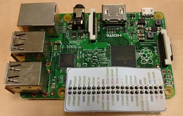
Visit the http://elinux.org/RPi_Low-level_peripherals webpage for detailed information about individual GPIO pins.
4.2.3 Monarco HAT
- module=MonarcoDrv
- classname=MonarcoHatDrv
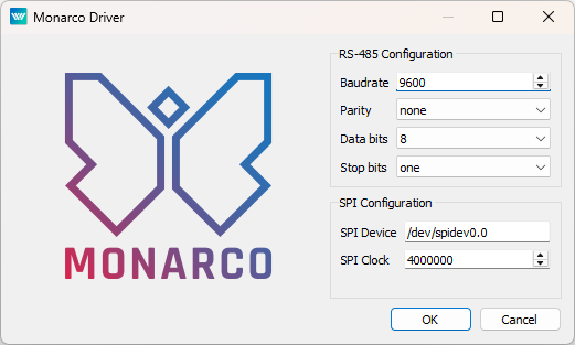
- cfgname=monarcohat.rio
- Recommended name IODRV and signals prefix: MNR
Remember to click the Configure button. This will create a default I/O driver configuration file (.rio). Keep the default values and close the dialog.
For the needs of the project, set the GotoTag parameters for the From blocks as:
- MNR__DI1 – The first physical switch is connected to DI1.
- MNR__DI3 – The second physical switch is connected to DI3.
The timer output will be routed to DO1 which will serve as the output signal. Set the Goto block (GotoTag = MNR__DO1).
Similarly for other inputs and outputs we could use the following flags:
- Goto, MNR__DO4 – digital output 4
- From, MNR__DI3 – digital input 3
- From, MNR__AI1 – analog input 1
A detailed description of the I/O driver for Monarco HAT is available in a separate manual [4].
The pinout of the Monarco HAT is shown in the following picture:
4.2.4 REX M527, Unipi Patron/Axon/Neuron
- module=MBDrv
- classname=MtmDrv
- cfgname=patron_cfg.rio
- Recommended name IODRV and signals prefix: PTN
You need to create the patron_cfg.rio file. Click the Configure button and fill the form as shown below. After that, click on OK and the file will be stored in the project folder.
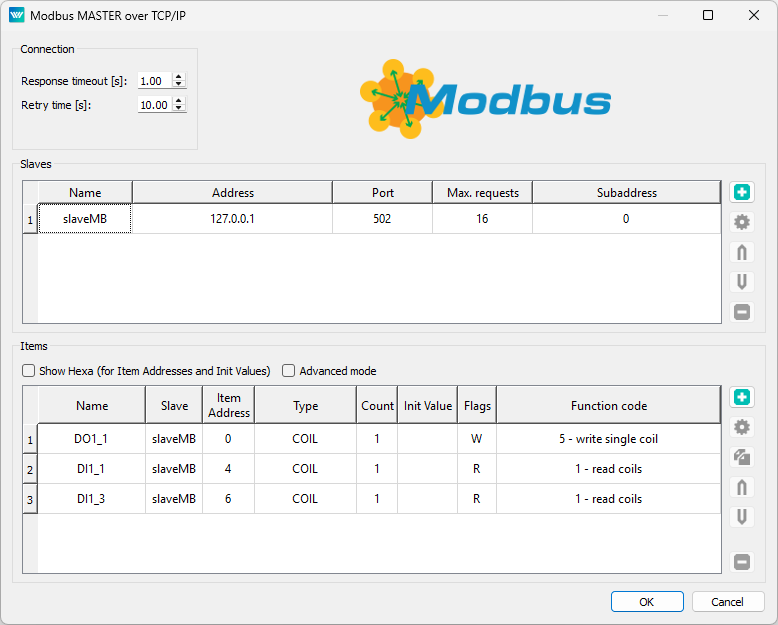
For the needs of the project, set the GotoTag parameters for the From blocks as:
- PTN__DI1_1 – The first physical switch is connected to first group of Digital Inputs - input 1.
- PTN__DI1_3 – The second physical switch is connected to Digital Input 1.3.
The timer output will be routed to Digital Output 1.1 and it will serve as the output signal. Set the Goto block (GotoTag = PTN__DO1_1).
Notice that the communication with the device is mediated by the Modbus TCP protocol. A detailed description of the driver for Modbus TCP is available in a separate manual [5].
Note: If you are using an older Unipi Axon or Neuron, the setup is the same. For clarity, you can use the prefix AXN, or NRN instead of PTN.
4.2.5 Weidmüller u-OS PLC (WL2000, M3000, M4000)
- module=UControlDrv
- classname=UControlDrv
- cfgname=weidmueller_cfg.rio
- Recommended name IODRV and signals prefix: WM
You need to create the weidmueller_cfg.rio file. Click the Configure button, then in the catalogue on the right-hand side, select the I/O modules you have connected one by one and arrange them after the PLC in the middle section in the correct order. Finally, click OK, and the file will be saved to the project folder.
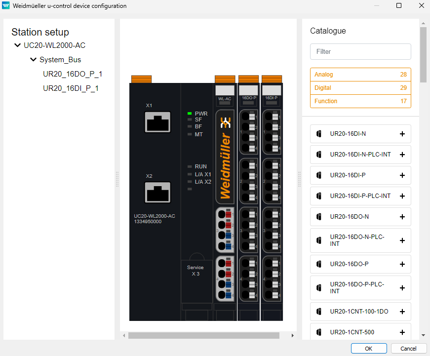
You should now have a new library prepared in the Block Library with the name of the driver, namely WM. Inside, you will find the generated From and Goto blocks according to the modules you added to the driver configuration. Select the From blocks:
- WM__UR20_16DI_P_1_Value_0 – The first physical switch is connected to the 16DI_P module on the first input.
- WM__UR20_16DI_P_1_Value_1 – The second physical switch is connected to the 16DI_P module on the second input.
The timer output will be connected to the 16DO_P module on the first output. Therefore, select the block WM__UR20_16DO_P_1_Value_0.
Chapter 5
Interacting with the algorithm
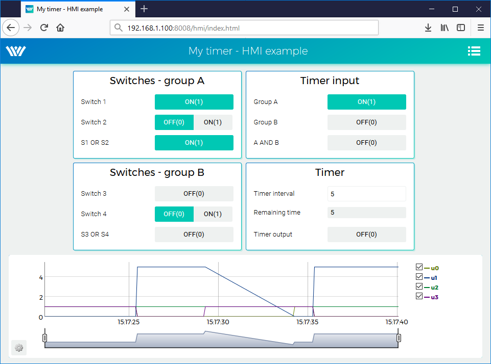
After compiling the project and downloading it to the platform, the control algorithm interacts with the physical world. Again it is possible to switch to Watch mode and observe the signals in real-time or analyze the trends of signals. Flip the physical switches and watch the signals.
Chapter 6
Updating the HMI
It is also necessary to update the HMI. The CNB_SWITCH1 and CNB_SWITCH3 blocks are no longer present in the algorithm. Moreover, we need to replace virtual input elements (DW) with indicators (DR). Therefore open the index.hmi.js file and replace
{type: 'DW', alias: 'switch1', desc: 'Switch 1', cstring: 'myproject_task.CNB_SWITCH1:YCN'},
with
{type: 'DR', alias: 'switch1', desc: 'Switch 1', cstring: 'myproject_task.OR_A:U1'},
Similarly for switch no. 3, replace
{type: 'DW', alias: 'switch3', desc: 'Switch 3', cstring: 'myproject_task.CNB_SWITCH3:YCN'},
with
{type: 'DR', alias: 'switch3', desc: 'Switch 3', cstring: 'myproject_task.OR_B:U1'},
Save the file, compile and download the project again and open the web interface. Push the two physical switches and wait until the timer triggers the output. Alternatively, you can still use the virtual switches. This demonstrates that you can combine physical and virtual input elements.
Chapter 7
Examples
Example projects and a set of all supported I/O flags are included in the installation package
of the REXYGEN system development tools. In REXYGEN Studio, go to menu File
Start
Start from an Example Project and select one of the platform’s examples. As
mentioned earlier, the most up-to-date information about examples are available
at
https://www.rexygen.com/example-projects/
Chapter 8
Next Steps
Congratulations on creating your first example project from scratch! You’ve learned how to develop, compile, and run your algorithms on the platform. You now know how to configure and work with the REXYGEN system’s I/O driver to interact with sensors and actuators. Additionally, you’ve gained experience in creating user interfaces with WebBuDi.
Impressive progress in a short time, right? The goal of these tutorials was to quickly introduce you to the essential steps and tools needed for project development. For the REXYGEN system, there is also a tool for creating visualizations - REXYGEN HMI Designer [6], which is suitable for more complex visualizations in larger projects. Details on creating visualizations in REXYGEN HMI Designer can be found in a separate manual [7].
Now it’s time to focus on your own project and deepen your understanding. There are functional blocks far more powerful than those introduced in this guide, many inspirational example projects, and additional I/O drivers to expand your project’s capabilities. You’ll also discover various ways to exchange data with external systems and devices, and much more.
Remember, whenever you achieve something you’d like to share, we’re always excited to hear about it. And whenever you run into a challenge, we’re here to help. Reach out to us anytime at support@rexygen.com.
Bibliography
[1] REX Controls s.r.o.. First Project, 2024. .
[2] REX Controls s.r.o.. Getting started with REXYGEN, 2024. .
[3] REX Controls s.r.o.. WagoDrv driver of REXYGEN for Wago PFC100/PFC200 – User guide, 2020. .
[4] REX Controls s.r.o.. MonarcoDrv driver of REXYGEN – User guide, 2020. .
[5] REX Controls s.r.o.. Modbus driver of REXYGEN – User guide, 2020. .
[6] REX Controls s.r.o.. REXYGEN HMI – User manual, 2024. .
[7] REX Controls s.r.o.. HMI creation in REXYGEN HMI Designer, 2024. .
Documentation reference number: 17159
2025 © REX Controls s.r.o., www.rexygen.com