Monarco HAT driver for the REXYGEN system
(the MonarcoDrv module)
User guide
Plzeň (Pilsen), Czech Republic
2025-07-04
Contents
1.1 Introduction
1.2 Installation
2 Including the driver in the project
2.1 Adding the MonarcoDrv driver
2.2 Connecting the inputs and outputs in the control algorithm
2.2.1 Example
3 Configuration of the MonarcoDrv driver
4 Drivers for bus pins
4.1 Modbus communication via RS-485
4.2 1-Wire sensors and expansion modules
5 Troubleshooting
Chapter 1
The MonarcoDrv driver and the REXYGEN system
1.1 Introduction
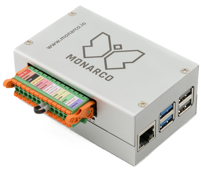
This manual explains how to use the MonarcoDrv driver for Monarco HAT [1] within the REXYGEN system, which was developed by REX Controls. The MonarcoDrv driver allows direct access to the inputs and outputs of the device.
If you are new to REXYGEN, we recommend starting with the tutorials Getting Started and Tutorials, which:
- Introduce you to the basic principles of the REXYGEN system and its development tools [2],
- Help you with the installation and configuration of the REXYGEN system on your target device [3],
- Show you how to create a simple project including a basic user interface [4],
- Demonstrate how to configure the inputs and outputs of your device [5],
- Enable you to create your own graphical user interface [6].
1.2 Installation
To configure the MonarcoDrv driver in the REXYGEN Studio development environment, ensure that the Monarco HAT driver option is checked during the REXYGEN Studio installation in the Select Components step. The easiest way is to select the Full installation option.
The MonarcoDrv driver is part of the standard RexCore installation on the target device (Raspberry Pi) and should be installed regardless of which installation method you chose as described in [3].
If for some reason you need to install MonarcoDrv separately, you can do so from the
Raspberry Pi command line using the command:
sudo apt-get install rex-monarcodrvt
Chapter 2
Including the driver in the project
The driver is included in the project as soon as the driver is added to the project main file and the inputs and outputs are connected in the control algorithm(s).
2.1 Adding the MonarcoDrv driver
The project main file with the MonarcoDrv driver included is shown in Figure 2.1.
There is one block which must be added to the project to include the driver. A block of type IODRV renamed to MNR and connected to the Drivers output of the main EXEC block. The name of this block (MNR, see Fig. 2.1), is the prefix of all input and output signals provided by this driver. After opening Block properties (double-click on the block), you can edit parameter settings. The four most important parameters are:
- module – name of the module linked to the driver, in this case MonarcoDrv
- classname – class of the driver, in this case MonarcoHatDrv
- cfgname – name of the driver configuration file, e.g. monarcohat.rio
- factor – multiple of the EXEC block’s tick parameter defining the driver’s task execution period
The Configure button opens the configuration dialog of the MonarcoDrv driver, which is described in chapter 3.
2.2 Connecting the inputs and outputs in the control algorithm
The inputs and outputs of the drivers can be connected to the algorithm in individual tasks using several function blocks:
- To read a single value, it is convenient to use the From block.
- The Goto block is used to write a single value.
- Since the driver allows obtaining several inputs or setting several outputs under one symbolic name, it is advantageous to use blocks of four-fold, eight-fold and sixteen-fold inputs and outputs (INQUAD, OUTQUAD, INOCT, OUTOCT and INHEXD, OUTHEXD). The advantage of such use is an increase in the speed and partly also the clarity of the algorithms.
The affiliation of the From and Goto blocks to a given driver is given by their parameter Goto tag, which starts with the name of this driver (see Fig. 2.1), continues with the separator __ (followed by two characters ’_’) and ends with the signal name defined in the driver configuration (see Chapter 3). For blocks INQUAD, OUTQUAD, INOCT, OUTOCT, INHEXD and OUTHEXD, this identification string is entered directly into their name. A detailed description of the blocks can be found in the [7] manual.
The tasks are then connected in the main project file to the QTask, Level0, Level1, Level2 and Level3 outputs of the EXEC block. The QTask and Level0 outputs are reserved for the highest priority tasks, the Level3 output for the lowest priority tasks.
2.2.1 Example
An example of accessing the inputs and outputs of the MonarcoDrv driver can be seen in Fig. 2.2. The function block From is used for reading, the function block Goto is used for writing the signal. Both of these blocks have a Goto tag parameter that is set to the name of the signal.
The figure shows two blocks of type From that allow the user to read inputs. These blocks have the Goto tag parameters set to MNR__DI1 and MNR__DI2. The name behind the underscores in the flag corresponds to the terminal pinout (terminal pinout is shown in Fig. 2.3). Next in the picture is a block of type Goto, which allows you to set (write) the output. Its Goto tag parameter is set to MNR__DO1.
Similarly for other pins we can use e.g. the flags:
- Goto, MNR__DO4 – digital output 4
- Goto, MNR__AO1 – analog output 1
- From, MNR__AI1 – analog input (voltage mode 0..10V)
- From, MNR__AI2C – analog input (current mode 0..20mA)
- Goto, MNR__LED5 – Onboard LED 5
- Goto, MNR__LED5_Mask – To control the built-in LED, it is necessary to set this parameter to TRUE
The installation of the REXYGEN system includes a library of examples, where among other things, the section 0121_Monarco_HAT is dedicated to the use of MonarcoDrv. The example 0121-00_IO_Flags contains a library of usable inputs and outputs.
Chapter 3
Configuration of the MonarcoDrv driver
The configuration dialog can be activated by pressing the Configure button in the parameters dialog of the IODRV block (see Chapter 2.1).
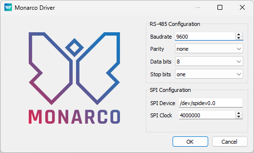
The RS-485 section configures the properties of the RS-485 bus for connecting to external devices.
IMPORTANT: Note that the internal communication between the CPU and the MCU of the Monarco HAT uses UART communication (/dev/ttyAMA0 on the Raspberry Pi) at 115200 baudrate, 8 bits per byte, no parity, 1 stop bit. These are the values you have to use in the Modbus driver configuration if you are willing to use it. For details about the internal structure of the Monarco HAT visit https://www.monarco.io.
The SPI configuration section defines the communication between the CPU and the Monarco HAT MCU (/dev/spidev0.0 on the Raspberry Pi, maximum clock speed is 4 MHz).
Chapter 4
Drivers for bus pins
In addition to analog and digital inputs and outputs, the Monarco HAT also provides RS-485 and 1-Wire bus pin connectivity. There are special drivers for these bus pins in the REXYGEN system. An example of connecting multiple controllers to the main project file can be seen in Fig. 4.1.
4.1 Modbus communication via RS-485
The RS-485 bus provides a standard interface to communicate with external devices (servo drives, energy meters, etc.) or to expand the I/O capabilities of the Monarco HAT itself. Modbus communication is typically used. There is a separate driver for Modbus communication in the REXYGEN system, see [8].
IMPORTANT: Note that the internal communication between the CPU and the MCU of the Monarco HAT uses UART communication (/dev/ttyAMA0 on the Raspberry Pi) at 115200 baudrate, 8 bits per byte, no parity, 1 stop bit. These are the values you have to use in the Modbus driver configuration if you are willing to use it. For details about the internal structure of the Monarco HAT visit https://www.monarco.io.
4.2 1-Wire sensors and expansion modules
The 1-Wire bus provides additional interface to expand the I/O capabilities of the Monarco HAT itself (e.g. using 1-Wire temperature sensors, relative humidity sensors, relay modules etc.). There is a separate driver for 1-Wire communication in the REXYGEN system, see [9].
Chapter 5
Troubleshooting
First and foremost, it’s advisable to explore the library of examples, especially the section 0121_Monarco_HAT, which pertains to the usage of MonarcoDrv.
In the case that the diagnostic tools of the REXYGEN system (e.g. REXYGEN Studio) report unexpected or incorrect values of inputs or outputs, it is desirable to check the configuration. The most common problems include:
- Hardware problem – incorrect wiring.
- Internal communication problem – SPI bus, I2C bus or UART is occupied by another service or program.
If you are unable to find the error, please send information about the problem by email to the address support@rexygen.com. To resolve the issue as quickly as possible, the information should include:
- Identification of the REXYGEN system you are using. Simply export it to a file using the REXYGEN Studio program (Target Licensing Export).
- Short and accurate description of your problem.
- The configuration files of the REXYGEN system (.mdl and .rio files) reduced to the simplest case which still demonstrates the problematic behavior.
Bibliography
[1] REX Controls s.r.o.. Internet webpage www.monarco.io, 2024.
[2] REX Controls s.r.o.. Getting started with REXYGEN, 2024. .
[3] REX Controls s.r.o.. RexCore (REXYGEN runtime core) Installation, 2024. .
[4] REX Controls s.r.o.. First Project, 2024. .
[5] REX Controls s.r.o.. I/O Configuration of Target Platforms, 2024. .
[6] REX Controls s.r.o.. HMI creation in REXYGEN HMI Designer, 2024. .
[7] REX Controls s.r.o.. Function blocks of REXYGEN – reference manual, 2024. .
[8] REX Controls s.r.o.. Modbus driver of REXYGEN – User guide, 2020. .
[9] REX Controls s.r.o.. OwsDrv driver of REXYGEN for 1-Wire devices – User guide, 2020. .
Documentation reference number: 17331
2025 © REX Controls s.r.o., www.rexygen.com