Raspberry Pi driver for the REXYGEN system
(the RPiDrv module)
User guide
2025-07-04
Plzeň (Pilsen), Czech Republic
Contents
1.1 Introduction
1.2 Installation
2 Including the driver in the project
2.1 Adding the RPiDrv driver
2.2 Connecting the inputs and outputs in the control algorithm
2.2.1 Example of Raspberry Pi GPIO pin connections
2.2.2 Example of connecting the PiFace Digital expansion board
2.2.3 Example of connecting the Unipi v1.1 expansion board
2.2.4 Example of connecting the Pigeon PLC
2.2.5 Example of connecting the Intellisys PIO expansion board
3 Troubleshooting
Chapter 1
The RPiDrv driver and the REXYGEN system
1.1 Introduction
This guide describes the use of the RPiDrv driver to expose the GPIO pins of the Raspberry Pi minicomputer (Raspberry Pi is a registered trademark of Raspberry Pi Foundation.) in the REXYGEN Control System. The driver allows both input and output pin modes and is compatible with Raspberry Pi 1-4 models. For Raspberry Pi 5, it is necessary to use the driver described in [1]. The RPiDrv driver also supports expansion boards Unipi v1.1 [2], PiFace Digital 1/2 [3], Intellisys PIO [4] and Pigeon PLC [5], based on Raspberry Pi. The driver was developed by REX Controls.
If you are new to REXYGEN, we recommend starting with the tutorials Getting Started and Tutorials, which:
- Introduce you to the basic principles of the REXYGEN system and its development tools [6],
- Help you with the installation and configuration of the REXYGEN system on your target device [7],
- Show you how to create a simple project including a basic user interface [8],
- Demonstrate how to configure the inputs and outputs of your device [9],
- Enable you to create your own graphical user interface [10].
1.2 Installation
To be able to configure the RPiDrv driver in the REXYGEN Studio development environment, it is necessary to have the Raspberry Pi driver option checked in the Select Components step during the REXYGEN Studio installation. The easiest is to select the Full installation option.
The RPiDrv driver is part of the standard RexCore installation on the target device (Raspberry Pi) and should be installed regardless of the installation method described in [7].
If for some reason you need to install RPiDrv separately, you can do so from the Raspberry
Pi command line using the command:
sudo apt-get install rex-rpidrvt
Chapter 2
Including the driver in the project
The driver is included in the project as soon as the driver is added to the project main file and the inputs and outputs are connected in the control algorithms.
2.1 Adding the RPiDrv driver
The project main file with the RPiDrv driver included is shown in Figure 2.1.
The block of type IODRV connected to the Drivers output of the main EXEC block is used to include the driver in the project. After opening Block properties (by double-clicking on the block), you can edit the parameter settings. The four most important parameters of the IODRV block are:
- module – name of the module linked to the driver, in this case RPiDrv
- classname – class of the driver
- RPiDrv – Raspberry Pi GPIO or PiFace Digital expansion board
- UnpDrv – Unipi v1.1 expansion board
- PioDrv – Intellisys PIO
- PgnDrv – Pigeon PLC
- cfgname – name of the driver configuration file, but this driver does not use any so leave it blank
- factor – multiple of the EXEC block’s tick parameter defining the driver’s task execution period.
Note: PiFace Digital, Unipi 1.1, Pigeon PLC and Intellisys PIO devices are considered deprecated and are not actively tested. We recommend using Monarco HAT.
All input and output signals of this driver begin with name of the IODRV block (see Fig. 2.1). It is recommended to rename the IODRV block according to the used platform:
- RPI – Raspberry Pi GPIO or PiFace Digital expansion board
- UNP – Unipi v1.1 expansion board
- PIO – Intellisys PIO
- PGN – Pigeon PLC
2.2 Connecting the inputs and outputs in the control algorithm
The inputs and outputs of the drivers can be connected to the algorithm in individual tasks using several function blocks:
- To read a single value, it is convenient to use the From block.
- The Goto block is used to write a single value.
- Since the driver allows obtaining several inputs or setting several outputs under one symbolic name, it is advantageous to use blocks of four-fold, eight-fold and sixteen-fold inputs and outputs (INQUAD, OUTQUAD, INOCT, OUTOCT and INHEXD, OUTHEXD). The advantage of such use is an increase in the speed and partly also the clarity of the algorithms.
The affiliation of the From and Goto blocks to a given driver is given by their parameter Goto tag, which starts with the name of this driver (see Fig. 2.1), continues with the separator __ (followed by two characters ’_’) and ends with the signal name. For blocks INQUAD, OUTQUAD, INOCT, OUTOCT, INHEXD and OUTHEXD, this identification string is entered directly into their name. A detailed description of the blocks can be found in the [11] manual.
The tasks are then connected in the main project file to the QTask, Level0, Level1, Level2 and Level3 outputs of the EXEC block. The QTask and Level0 outputs are reserved for the highest priority tasks, the Level3 output for the lowest priority tasks.
Below are examples for each platform supported by the RPiDrv driver. The examples use the From function block for reading, and the Goto function block for signal writing. Both of these blocks have a Goto tag parameter that is set to the name of the signal.
2.2.1 Example of Raspberry Pi GPIO pin connections
Due to the variability of GPIO compared to classic inputs and outputs, the above-described method of setting Goto tag is supplemented with an optional letter at the end. Depending on the letter, the following properties are set:
- U – activation of the pull-up resistor at the input,
- D – activation of the pull-down resistor at the input,
- H – setting the initial state of the output to logical 1 (on),
- L – setting the initial state of the output to logical 0 (off).
An example of use can be seen in Fig. 2.2. For more information on GPIO pins, visit http://elinux.org/RPi_Low-level_peripherals.
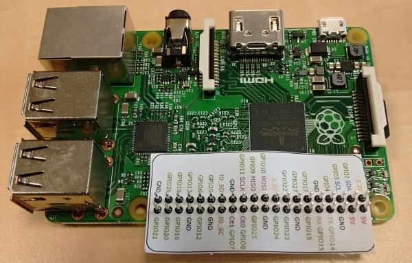
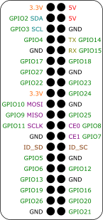
One From block used to connect a single input has its Goto tag parameter set to RPI__GPIO21U, while another block has it set to RPI__GPIO22U. The name following the underscores in the tag corresponds to the designated GPIO pin (the pin numbering is shown in Fig. 2.3). The Goto block, used to connect a single output, has its Goto tag parameter set to RPI__GPIO23.
Similarly, for other pins we can use, for example, the following flags:
- Goto, RPI__GPIO22 – digital output 22
- Goto, RPI__GPIO23H – digital output 23, which is set to logical 1 (HIGH, ON) immediately upon initialization
- Goto, RPI__PWM18 – PWM output on pin 18
- From, RPI__GPIO7U – digital input 7 with internal pull-up resistor
- From, RPI__GPIO8D – digital input 8 with internal pull-down resistor
- From, RPI__GPIO21 – digital input 21 without any internal pull-up/down resistor
The installation of the REXYGEN system includes a library of examples, where among other things, the section 0120_Raspberry_Pi is dedicated to the use of RPiDrv. The example 0120-00_IO_Flags contains a library of usable inputs and outputs.
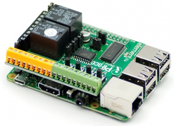
2.2.2 Example of connecting the PiFace Digital expansion board
In contrast to the input and output naming convention described above, the PiFace Digital board allows you to add the optional letter U to the end of the input name to activate the pull-up resistor. An example of use can be seen in Fig. 2.4.
One From block used to connect a single input has the Goto tag parameter set to RPI__PFI0U, while the other is set to RPI__PFI1U. The name behind the underscores in the tag corresponds to the name of the used terminal pin (the pin designation can be seen in Fig. 2.3). The Goto type block used to connect one output has the Goto tag parameter value set to RPI__PFO3.
Note: It is also possible to read/write all eight inputs/outputs of PiFace Digital at once. This is faster than working with the individual signals. In that case the user must use the INOCT and OUTOCT blocks named RPI__PFI and RPI__PFO respectively.
The installation of the REXYGEN system includes a library of examples, where among other things, the section 0124_PiFace_Digital is dedicated to the use of RPiDrv. The example 0124-00_IO_Flags contains a library of usable inputs and outputs.
Using Multiple PiFace Digital Boards at Once: In the default configuration, it is assumed that the PiFace Digital board address is set to 0. If this is not the case, the address must be specified in the input/output flags. For example, RPI__PFO3C2 refers to the fourth output of the PiFace Digital board with the address 2.
2.2.3 Example of connecting the Unipi v1.1 expansion board
An example of accessing the inputs and outputs of the Unipi v1.1 expansion board is shown in Fig. 2.6.
One From block used to connect a single input has the Goto tag parameter set to UNP__I01, while the other is set to UNP__I03. The name behind the underscores in the tag corresponds to the name of the used terminal pin (the pin designation can be seen in Fig. 2.7). The Goto type block used to connect one output has the Goto tag parameter value set to UNP__RLY1.
The installation of the REXYGEN system includes a library of examples, where among other things, the section 0122_UniPi_1 is dedicated to the use of RPiDrv. The example 0122-00_IO_Flags contains a library of usable inputs and outputs.
2.2.4 Example of connecting the Pigeon PLC
An example of accessing the inputs and outputs of the Pigeon PLC is shown in Fig. 2.8.
One From block used to connect a single input has the Goto tag parameter set to PGN__ID1, and another to PGN__ID3. The name following the underscores in the tag corresponds to the name of the terminal pin used (the pin designation is shown in Fig. 2.9). The Goto block used to connect a single output has the Goto tag parameter set to PGN__O1.
The installation of the REXYGEN system includes a library of examples, among which the 0123_Pigeon_PLC section is dedicated to using RPiDrv with the Pigeon PLC. The 0123-00_IO_Flags example contains a library of usable input and output settings.
2.2.5 Example of connecting the Intellisys PIO expansion board
An example of accessing the inputs and outputs of the Intellisys PIO expansion board is shown in Fig. 2.10.
One From block used to connect a single input has the Goto tag parameter set to PIO__DI1, and another to PIO__DI2. The name following the underscores in the tag corresponds to the name of the terminal pin used (the pin designation is shown in Fig. 2.11). The Goto block used to connect a single output has the Goto tag parameter set to PIO__DO1.
The installation of the REXYGEN system includes a library of examples, among which the 0125_Intellisys_PIO section is dedicated to using RPiDrv with the Intellisys PIO expansion board. The 0125-00_IO_Flags example contains a library of usable input and output settings.
Chapter 3
Troubleshooting
First and foremost, it is advisable to explore the example libraries related to using RPiDrv with the specific device.
If unexpected or incorrect input or output values appear in the diagnostic tools of the REXYGEN system, it is recommended to verify their functionality independently of the REXYGEN system. Furthermore, the configuration should be carefully checked. The most common errors include:
- Hardware error – incorrect wiring.
- Pin access error – the pin is being used by another device (SPI bus, I2C bus, serial port) or by another program.
In the case that the given input or output works with other software tools and does not work in the REXYGEN system, report the problem to us, please. E-mail is preferred, reach us at support@rexygen.com. Please include the following information in your description to help us process your request as soon as possible:
- Identification of the REXYGEN system you are using. Simply export it to a file using the REXYGEN Studio program (Target Licensing Export).
- Short and accurate description of your problem.
- The configuration files of the REXYGEN system (.mdl files) reduced to the simplest case which still demonstrates the problematic behavior.
Bibliography
[1] REX Controls s.r.o.. GPIO driver for the REXYGEN system – User guide, 2024. .
[2] Unipi Technology s.r.o. Unipi technology. http://www.unipi.technology, 2024. .
[3] University of Manchester. PiFace Digital Interface. http://www.piface.org.uk, 2013. .
[4] Intellisys S.r.l. PIO programmable input-output interface. http://www.intellisys.it, 2014.
[5] Kristech. Pigeon PLC. http://www.pigeoncomputers.com, 2024. .
[6] REX Controls s.r.o.. Getting started with REXYGEN, 2024. .
[7] REX Controls s.r.o.. RexCore (REXYGEN runtime core) Installation, 2024. .
[8] REX Controls s.r.o.. First Project, 2024. .
[9] REX Controls s.r.o.. I/O Configuration of Target Platforms, 2024. .
[10] REX Controls s.r.o.. HMI creation in REXYGEN HMI Designer, 2024. .
[11] REX Controls s.r.o.. Function blocks of REXYGEN – reference manual, 2024. .
Documentation reference number: 17331
2025 © REX Controls s.r.o., www.rexygen.com