RM_Axis – Motion control axis
Block SymbolLicensing group: MOTION CONTROL

Function Description
The RM_AXIS block is a cornerstone of the motion control solution within the REXYGEN
system. This base block keeps all status values and implements basic algorithm for one motion
control axis (one motor), which includes limits checking, emergency stop, etc. The block is
used for both real and virtual axes. The real axis must have a position feedback controller,
which is out of this block’s scope. The key status values are commanded position, velocity,
acceleration and torque, as well as state of the axis, axis error code and a reference to the
block, which controls the axis.
This block (like all blocks in the motion control library) does not implement a feedback controller which would keep the actual position as near to the commanded position as possible. Such a controller must be provided by using other blocks (e.g. PIDU) or external (hardware) controller. The feedback signals are used for lag checking, homing and could be used in special motion control blocks. The feedback signals are connected throw the RM_AxisSpline block.
The parameters of this block correspond with the requirements of the PLCopen standard for an axis. If improper parameters are set, the errorID output is set to -700 (invalid parameter) and all motion blocks fail with -703 error code (invalid state).
The parameters for limit velocity, acceleration and deceleration are twofold. One for application, e.g. limit value which could be set into movtion blocks. This value could be exceeded in some cases. Second limit is for system. The system limits must be higher then application limits and it is never exceeded. If some motion block generate path, that exceed system limit, error stop seqvence is activated.
Note that the default values for position, velocity and acceleration limits are intentionally set to , which makes them invalid. Limits must always be set by the user according to the real axis and the axis actuator.
Inputs
uChain | Input is not used by the block. User can connect any signal to define order of block’s execution | Long (I32) |
Outputs
axisRef | Axis reference (only RM_Axis.axisRef-uAxis or yAxis-uAxis connections are allowed) | Reference |
CommandedPosition | Requested (commanded) position of the axis. The value is logical position that is put into the motion blocks. The position is different from PhysicalPosition if the axis is circular or homed. | Double (F64) |
CommandedVelocity | Requested (commanded) velocity of the axis | Double (F64) |
CommandedAcceleration | Requested (commanded) acceleration of the axis | Double (F64) |
CommandedTorque | Requested (commanded) torque in the axis | Double (F64) |
State | State of the axis | Long (I32) |
|
|
|
ErrorID | Result of the last operation | Error |
|
|
|
PhysicalPosition | Requested (commanded) position of the axis. The value is physical position that is put into the feedback controller. The position is different from CommandedPosition if the axis is circular or homed. | Double (F64) |
Parameters
AxisType | Type of the axis 1 | Long (I32) |
|
|
|
EnableLimitPos | Enable positive position limit checking (e.g. if checked, MaxPosAppl is valid) | Bool |
MaxPosAppl | Positive position limit for application (MC blocks). The value should be smaller then (before the) MaxPosSystem for linear axis. The value limit cyclic axis with linear senzor for few revolution (useful for robotic application) and must be bigger then (beyond the) MaxPosSystem. | Double (F64) |
MaxPosSystem | Positive position limit for system. The value is never exceeded for linear axis. The value is end of revolution for cyclic axis. | Double (F64) |
EnableLimitNeg | Enable negative position limit checking (e.g. if checked, MinPosAppl is valid) | Bool |
MinPosAppl | Negative position limit for application (MC blocks) The value should be bigger then (before the) MinPosSystem for linear axis. The value limit cyclic axis with linear senzor for few revolution (useful for robotic application) and must be smaller then (beyond the) MinPosSystem. | Double (F64) |
MinPosSystem | Negative position limit for system. The value is never exceeded for linear axis. The value is begin of revolution for cyclic axis. | Double (F64) |
EnablePosLagMonitor | Enable monitoring of position lag (e.g. if checked, MaxPositionLag is valid) | Bool |
MaxPositionLag | Maximal position lag. Any moving is stopped and the axis is switched into error stop state if different between PhysicalPosition and ActualPosition exceed this value. | Double (F64) |
MaxVelocitySystem | Maximal allowed velocity for system | Double (F64) |
MaxVelocityAppl | Maximal allowed velocity for application (MC blocks) | Double (F64) |
MaxAccelerationSystem | Maximal allowed acceleration for system | Double (F64) |
MaxAccelerationAppl | Maximal allowed acceleration for application (MC blocks) | Double (F64) |
MaxDecelerationSystem | Maximal allowed deceleration for system | Double (F64) |
MaxDecelerationAppl | Maximal allowed deceleration for application (MC blocks) | Double (F64) |
DefaultJerk | Maximal recomended jerk [unit/]. Real jerk is not checked and could overcome this value. | Double (F64) |
MaxTorque | Maximal motor torque/force (0=not used) | Double (F64) |
TorqueRatio | Torque-Acceleration ratio. The requested torque value is useful for feedback controller. The most block don’t generate it. The requested torque value is comuted as reqested acceleration multiplied by this parameter. | Double (F64) |
LoopDelay | delay between commanded and actual values[s] The actual position value is deleyed from commanded value due communication with feedback controller, feedback loop, value interpolation and sampling period. The delay could be set into this parameter and then position lag is computed more precisely. (not yet implemented) | Double (F64) |
StartMode | Some options when axis is enabled 1 | Long (I32) |
|
|
|
HomingRequired | Homing is required before any move | Bool |
Example
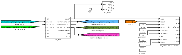
Following example illustrates basic principle of use of motion control blocks. It presents the
minimal configuration which is needed for operation of a physical or virtual axis. The axis is
represented by RM_Axis block. The limitations imposed on the motion trajectory in form of
maximum velocity, acceleration, jerk and position have to be set in parameters of the RM_Axis
block. The inputs can be connected to supply the values of actual position, speed and torque
(feedback for slip monitoring) or logical limit switch signals for homing procedure. The
axisRef output signal needs to be connected to any motion control block related to the
corresponding axis. The axis has to be activated by enabling the MC_Power block. The state
of the axis changes from Disabled to Standstill (see the following state transition
diagram) and any discrete, continuous or synchronized motion can be started by
executing a proper functional block (e.g. MC_MoveAbsolute). The trajectory of motion in
form of desired position, velocity and acceleration is generated in output signals of
the RM_Axis block. The reference values are provided to an actuator control loop
which is implemented locally in REXYGEN system in the same or different task
or they are transmitted via a serial communication interface to end device which
controls the motor motion (servo amplifier, frequency inverter etc.). In case of any
error, the axis performs an emergency stop and indicates the error ID. The error has
to be confirmed by executing the MC_Reset block prior to any subsequent motion
command. The following state diagram demonstrates the state transitions of an
axis.
Axis state transition diagram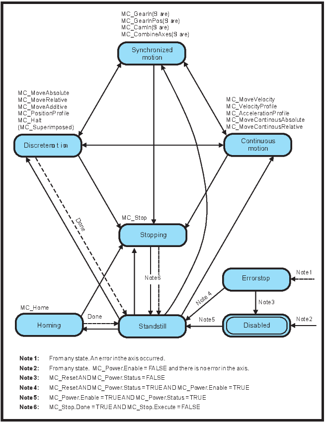
Motion blending
According to PLCOpen specification, number of motion control blocks allow to specify
BufferMode parameter, which determines a behaviour of the axis in case that a motion
command is interrupted by another one before the first motion is finished. This transition from
one motion to another (called "Blending") can be handled in various ways. The following table
presents a brief explanation of functionality of each blending mode and the resulting shapes of
generated trajectories are illustrated in the figure. For detailed description see full PLCOpen
specification.
| Aborting | The new motion is executed immediately |
| Buffered | the new motion is executed immediately after finishing the previous one, there is no blending |
| Blending low | the new motion is executed immediately after finishing the previous one, but the axis will not stop between the movements, the first motion ends with the lower limit for maximum velocity of both blocks at the first end-position |
| Blending high | the new motion is executed immediately after finishing the previous one, but the axis will not stop between the movements, the first motion ends with the higher limit for maximum velocity of both blocks at the first end-position |
| Blending previous | the new motion is executed immediately after finishing the previous one, but the axis will not stop between the movements, the first motion ends with the limit for maximum velocity of first block at the first end-position |
| Blending next | the new motion is executed immediately after finishing the previous one, but the axis will not stop between the movements, the first motion ends with the limit for maximum velocity of second block at the first end-position |
Illustration of blending modes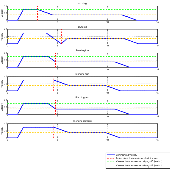
[Back to top] [Up] [Next]
2023 © REX Controls s.r.o., www.rexygen.com