IPEN2, IPEN3 – N-link inverted pendulum on cart - Physical parameters
Block SymbolsLicensing group: MODEL


Function Description
The IPEN2 and IPEN3 blocks simulate the dynamics of double and triple inverted
pendulums on a cart, respectively. These models enable users to conduct experiments with
various control strategies, making them suitable for both educational and research
purposes.
The primary input to the models is an analog signal u, interpreted based on the IACC parameter setting:
- for IACC=on, the input u is assumed to be a force acting on the cart [N],
- for IACC=off, the models assume the input represents speed [m/s].
The R1 signal is used to reset each model to its initial configuration.
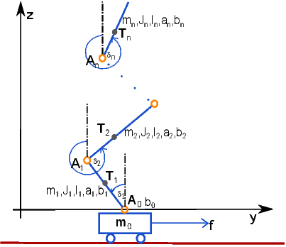
Both models can be precisely configured with a series of parameters that reflect the system’s physical characteristics. These include the relative center of gravity positions a, moments of inertia J, lengths l, and masses of the pendulums m, as well as damping coefficients b and the initial state of the system (positions d_0, velocities dd_0). A schematic representation of the system with parameters is shown below. The parameters are intuitively defined. The relative position of the center of gravity for the i-th pendulum, , is determined by the equation
where is the position of the previous joint, is the position of the pendulum’s center of gravity, and is the length of the pendulum.
The computation of the models adheres to the mathematical model and physical parameters detailed in the literature [6]. The IPEN2pu and IPEN3pu blocks are used for simulating the inverted pendulum models with dynamic parameters.
This block does not propagates the signal quality. More information can be found in the 1.4 section.
Input
u | Analog input of the block | Double (F64) |
R1 | Block reset | Bool |
Parameter
a1 | Relative position of center of gravity 1.0 | Double (F64) |
a2 | Relative position of center of gravity 1.0 | Double (F64) |
a3 | Relative position of center of gravity 1.0 | Double (F64) |
J1 | Moment of inertia of pendulum 1.0 | Double (F64) |
J2 | Moment of inertia of pendulum 1.0 | Double (F64) |
J3 | Moment of inertia of pendulum 1.0 | Double (F64) |
l1 | Length of pendulum [m] 1.0 | Double (F64) |
l2 | Length of pendulum [m] 1.0 | Double (F64) |
l3 | Length of pendulum [m] 1.0 | Double (F64) |
m1 | Mass of pendulum [kg] 1.0 | Double (F64) |
m2 | Mass of pendulum [kg] 1.0 | Double (F64) |
m3 | Mass of pendulum [kg] 1.0 | Double (F64) |
m0 | Mass of cart [kg] 1.0 | Double (F64) |
b1 | Damping coefficient of pendulum 1.0 | Double (F64) |
b2 | Damping coefficient of pendulum 1.0 | Double (F64) |
b3 | Damping coefficient of pendulum 1.0 | Double (F64) |
b0 | Damping coefficient of cart 1.0 | Double (F64) |
d1_0 | Initial angle of pendulum [rad] 1.0 | Double (F64) |
d2_0 | Initial angle of pendulum [rad] 1.0 | Double (F64) |
d3_0 | Initial angle of pendulum [rad] 1.0 | Double (F64) |
x_0 | Initial position of cart [m] 1.0 | Double (F64) |
dd1_0 | Initial angular velocity of pendulum [rad/s] 1.0 | Double (F64) |
dd2_0 | Initial angular velocity of pendulum [rad/s] 1.0 | Double (F64) |
dd3_0 | Initial angular velocity of pendulum [rad/s] 1.0 | Double (F64) |
dx_0 | Initial velocity of cart [m/s] 1.0 | Double (F64) |
IACC | on=Input u is velocity, off=Input u is force | Bool |
Output
d1 | Angle of pendulum [rad] | Double (F64) |
d2 | Angle of pendulum [rad] | Double (F64) |
d3 | Angle of pendulum [rad] | Double (F64) |
x | Position of cart [m] | Double (F64) |
dd1 | Angular velocity of pendulum [rad/s] | Double (F64) |
dd2 | Angular velocity of pendulum [rad/s] | Double (F64) |
dd3 | Angular velocity of pendulum [rad/s] | Double (F64) |
dx | Velocity of cart [m/s] | Double (F64) |
E | Error indicator | Bool |
[Previous] [Back to top] [Up] [Next]
2024 © REX Controls s.r.o., www.rexygen.com