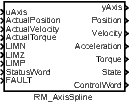
RM_AxisSpline – Commanded values interpolation
Block SymbolLicensing group: MOTION CONTROL
Function Description
The purpose of the block is to connect a virtual axis (represented by the RM_Axis block) to the motor or rather the servo drive and transform virtual axis into physical one. It includes some independent functions that are covered by this block.
The block has commanded and actual (feedback) signals to connect feedback controller. It includes inputs ActualPosition, ActualVelocity, ActualTorque and outputs Position, Velocity, Acceleration, Torque.
The feedback controller or servo drive usually works with different units (position unit is usually in encoder’s tick that is transformed by gear ratio). The RM_AxisSpline block transforms drive unit into axis logical unit. The function is controlled by the DriveUnits and AxisUnits parameters.
The servo drive often uses integer types for compute or communicate position, velocity and torque. Position can overflow range of integer value when motor is running one direction long time. The RM_AxisSpline block expects this situation and set correct position if feedback signal overflow from maximum integer value to minimal integer value. This feature is controlled by the DriveBits and must be also supported by the servo drive to work correctly.
The servo drive has different working state and operation mode and require some sequence to switch into operation mode where motor follow requested position. The most common standard for the mode and sequencing is CiA402. The RM_AxisSpline block support the CiA402 standard by the StatusWord input, the ControlWord output and the DriveMode, DriveTimeout parameters. The servo drive must be set to Cyclic Synchronous Position Mode (or mode with similar functionality). There is also possible to use Velocity Mode, but position loop regulator must be realized in control system (typically by a PIDU block).
There are a lot of motion control blocks which implement complicated algorithms so they require bigger sampling period (typical update rate is from 10 to 200 ms). On the other side, the motor driver usually requires small sampling period for smooth/waveless movement. The RM_AxisSpline block solves this problem of multirate execution of motion planning and motion control levels. The block can run in another task than other motion control blocks with highest possible sampling period. It interpolates commanded position, velocity, acceleration and torque and generates smooth curve which is more suited for motor driver controllers.
There are many possibilities how to compute position (and velocity, acceleration, torque) between sampled points by slower task. This could be chosen by the InterpolationMode parameter, but torque is interpolated always by linear function. The supported methods include:
- linear: Position is interpolated linearly, velocity as the derivative of position, acceleration is 0 (i.e., velocity is a piecewise constant function with jumps).
- cubic spline: Position is a 3rd order polynomial calculated based on the position and velocity at the beginning and end of the interval; velocity is the derivative of position, acceleration is the derivative of velocity.
- quintic spline: Position is a 5th order polynomial calculated based on the position, velocity, and acceleration at the beginning and end of the interval; velocity is the derivative of position, acceleration is the derivative of velocity.
- cubic aproximation (B-spline): Position is a 3rd order polynomial calculated based on two positions before and two positions after the current interval; the interpolated function may not exactly pass through the given points; velocity is the derivative of position, acceleration is the derivative of velocity.
- quintic aproximation (B-spline): Position is a 5th order polynomial calculated based on three positions before and three positions after the current interval; the interpolated function may not exactly pass through the given points; velocity is the derivative of position, acceleration is the derivative of velocity.
- all linear: Position, velocity, and acceleration are independently interpolated linearly, i.e., velocity does not precisely correspond to the derivative of position, and acceleration does not precisely correspond to the derivative of velocity.
- all cubic: Both position and velocity are interpolated by a 3rd order polynomial independently, i.e., velocity does not exactly correspond to the derivative of position.
- reserved for future use.
- reserved for future use.
Most simple is linear interpolation, but it leads to steps in velocity. Better possibility is higher order polynom (e.g. 3th or 5th order). It generates a smooth curve, but leads to a huge acceleration if the original trajectory isn’t the same polynomial. Drawback of polynomial interpolation could be solved by Bspline approximation, but it requires more samples and therefore bigger delay. Some original position values can be changed with this method.
Note 1: Because the execution time of motion blocks is varying in time, the block uses one or two step prediction for interpolation depending on actual conditions and timing of the motion blocks in slower tasks. The use of predicted values is signalized by states Run1, Run2, Run3.
Note 2: The interpolation functionality requires to put the block into different (faster) task than RM_Axis. For this reason, the block RM_AxisSpline has an internally safe solution for connecting axis references by the block Inport and Outport between different tasks.
Input
uAxis | Axis reference (only RM_Axis.axisRef–uAxis or yAxis–uAxis connections are allowed) | Reference |
ActualPosition | Current position of the axis (feedback) [drive unit] | Double (F64) |
ActualVelocity | Current velocity of the axis (feedback) [drive unit/s] | Double (F64) |
ActualTorque | Current torque in the axis (feedback) | Double (F64) |
LIMN | Limit switch in negative direction | Bool |
LIMZ | Absolute switch or reference pulse for homing | Bool |
LIMP | Limit switch in positive direction | Bool |
StatusWord | Status register for drive control according CiA402 specification | Long (I32) |
FAULT | External fault signal | Bool |
Outputs
yAxis | Axis reference (only RM_Axis.axisRef–uAxis or yAxis–uAxis connections are allowed) | Reference |
Position | Commanded interpolated position [drive unit] | Double (F64) |
Velocity | Commanded interpolated velocity [drive unit/s] | Double (F64) |
Acceleration | Commanded interpolated acceleration [drive unit/s/s] | Double (F64) |
Torque | Commanded interpolated torque/force | Double (F64) |
State | Interpolator state/error | Long (I32) |
|
|
|
ControlWord | Control register for drive control according CiA402 specification | Long (I32) |
Parameters
InterpolationMode | Algorithm for interpolation 9 | Long (I32) |
|
|
|
ReverseLimit | Invert meaning of LIMN, LIMZ and LIMP inputs | Bool |
InterpolationMode | Drive control mode 9 | Long (I32) |
|
|
|
DriveTimeout | Drive control response timeout [s] (for Strict CiA402 mode only) | Double (F64) |
DriveBits | number of valid bits (negative value means signed number) in the Position output and the ActualPosition input -64 63 -32 | Long (I32) |
DriveUnits | Distance in drive units for position transformation (value correspond to AxisUnits) | Double (F64) |
AxisUnits | Distance in axis units for position transformation (value correspond to DriveUnits) | Double (F64) |
VelocityCalculate | if checked, the input ActualVelocity is ignored and velocity is calculated by actual position difference | Bool |
[Previous] [Back to top] [Up] [Next]
2024 © REX Controls s.r.o., www.rexygen.com