TIMER – Multipurpose timer
Block SymbolLicensing group: STANDARD

Function Description
The TIMER block either generates an output pulse of the given width pt (in seconds)
or filters narrow pulses in the U input signal whose width is less than pt seconds.
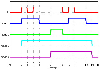
The operation mode is determined by the mode parameter. Supported modes are:
- Pulse: An output pulse of the length pt is generated upon rising edge at the U input. All input pulses during the generation of the output pulse are ignored.
- Delayed ON: The input signal U is copied to the Q output, but the start of the pulse is delayed by pt seconds. Any pulse shorter than pt is does not pass through the block.
- Delayed OFF: The input signal U is copied to the Q output, but the end of the pulse is delayed by pt seconds. If the break between two pulses is shorter than pt, the output remains on for the whole time.
- Delayed change: The Q output is set to the value of the U input no sooner than the input remains unchanged for pt seconds.
The graph illustrates the behaviour of the block in individual modes for :
The timer can be paused by the HLD input. The R1 input resets the timer. The reset signal overpowers the U input, similarly to the RS block.
This block propagates the signal quality. More information can be found in the 1.4 section.
Input
U | Trigger of the timer | Bool |
HLD | Timer hold | Bool |
R1 | Timer reset | Bool |
Parameter
mode | Timer mode 1 | Long (I32) |
|
|
|
pt | Timer interval [s] 1.0 | Double (F64) |
Output
Q | Timer output | Bool |
et | Elapsed time [s] | Double (F64) |
rt | Remaining time [s] | Double (F64) |
[Previous] [Back to top] [Up]
2024 © REX Controls s.r.o., www.rexygen.com