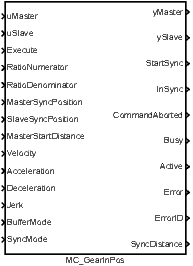
MC_GearInPos, MCP_GearInPos – Engage the master/slave velocity ratio in defined position
Block SymbolsLicensing group: MOTION CONTROL


Function Description
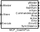
The MC_GearInPos and MCP_GearInPos blocks offer the same functionality, the only
difference is that some of the inputs are available as parameters in the MCP_ version of the
block.
The functional block MC_GearInPos engages a synchronized motion of master and slave axes in such a way that the ratio of velocities of both axes is maintained at a constant value. Compared to MC_GearIn, also the master to slave position ratio is determined in a given reference point, i.e. following relation holds:
In case that the slave position does not fulfill this condition of synchronicity at the moment of block activation (i.e. in an instant of positive edge of Execute input and after execution of previous commands in buffered mode), synchronization procedure is started and indicated by output StartSync. During this procedure, proper slave trajectory which results in smooth synchronization of both axes is generated with respect to actual master motion and slave limits for Velocity, Acceleration, Deceleration and Jerk (these limits are not applied from the moment of successful synchronization). Parameter setting MasterStartDistance=0 leads to immediate start of synchronization procedure at the moment of block activation (by the Execute input). Otherwise, the synchronization starts as soon as the master position enters the interval MasterSyncPosition MasterStartDistance.
Notes:
1. The synchronization procedure uses two algorithms: I. The algorithm implemented in
MC_MoveAbsolute is recomputed in every time instant in such a
way, that the end velocity is set to actual velocity of master axis. II. The position, velocity and
acceleration is generated in the same manner as in the synchronized motion and a proper 5th
order interpolation polynomial is added to achieve smooth transition to the synchronized state.
The length of interpolation trajectory is computed in such a way that maximum velocity,
acceleration and jerk do not violate the specified limits (for the interpolation polynomial). The
first algorithm cannot be used for nonzero acceleration of the master axis whereas the second
does not guarantee the compliance of maximum limits for the overall slave trajectory. Both
algorithms are combined in a proper way to achieve the synchronized motion of both
axes.
2. The block parameters (execution of synchronization and velocity/acceleration limits) have to be chosen so that the slave position is close to SlaveSyncPosition approximately at the moment when the master position enters the range for synchronization given by MasterSyncPosition and MasterStartDistance. Violation of this rule can lead to unpredictable behaviour of the slave axis during the synchronization or to an overrun of the specified limits for slave axis. However, the motion of both axes is usually well defined and predictable in standard applications and correct synchronization can be performed easily by proper configuration of motion commands and functional block parameters.
Inputs
uMaster | Master axis reference | Reference |
uSlave | Slave axis reference | Reference |
Execute | The block is activated on rising edge | Bool |
RatioNumerator | Gear ratio Numerator | Long (I32) |
RatioDenominator | Gear ratio Denominator | Long (I32) |
MasterSyncPosition | Master position for synchronization | Double (F64) |
SlaveSyncPosition | Slave position for synchronization | Double (F64) |
MasterStartDistance | Master distance for starting gear in procedure | Double (F64) |
Velocity | Maximal allowed velocity [unit/s] | Double (F64) |
Acceleration | Maximal allowed acceleration [unit/s] | Double (F64) |
Deceleration | Maximal allowed deceleration [unit/s] | Double (F64) |
Jerk | Maximal allowed jerk [unit/s] | Double (F64) |
BufferMode | Buffering mode | Long (I32) |
|
|
|
SyncMode | Synchronization mode (cyclic axes only) | Long (I32) |
|
|
|
Outputs
yMaster | Master axis reference | Reference |
ySlave | Slave axis reference | Reference |
StartSync | Commanded gearing starts | Bool |
InSync | Slave axis reached the cam profile | Bool |
CommandAborted | Algorithm was aborted | Bool |
Busy | Algorithm not finished yet | Bool |
Active | The block is controlling the axis | Bool |
Error | Error occurred | Bool |
ErrorID | Result of the last operation | Error |
|
|
|
SyncDistance | Position deviation of the slave axis from synchronized position | Double (F64) |
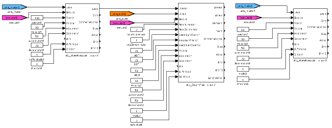
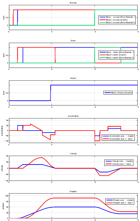
Example

[Previous] [Back to top] [Up] [Next]
2023 © REX Controls s.r.o., www.rexygen.com