PIDMA – PID controller with moment autotuner
Block SymbolLicensing group: AUTOTUNING

Function Description
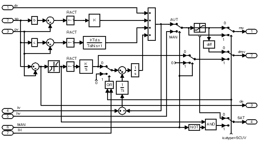
The PIDMA block has the same control function as the PIDU block. Additionally it
is equipped with the moment autotuning function.
In the automatic mode (), the block PIDMA implements the PID control law with two degrees of freedom in the form
where is Laplace transform of the manipulated variable mv, is Laplace transform of the setpoint variable sp, is Laplace transform of the process variable pv, is Laplace transform of the feedforward control variable dv and , , , , and are the parameters of the controller. The sign of the right hand side depends on the parameter RACT. The range of the manipulated variable mv (position controller output) is limited by parameters hilim, lolim. The parameter dz determines the dead zone in the integral part of the controller. The integral part of the control law can be switched off and fixed on the current value by the integrator hold input . For the proper function of the controller it is necessary to connect the output mv of the controller to the controller input tv and properly set the tracking time constant tt.
The rule of thumb for a PID controller is . For a PI controller the formula is . In this way we obtain the bumpless operation of the controller in the case of the mode switching (manual, automatic) and also the correct operation of the controller when saturation of the output mv occurs (antiwindup).
The additional outputs dmv, de and SAT generate the velocity output (difference of mv), deviation error and saturation flag, respectively.
If the PIDMA block is connected with the block SCUV to configure the 3-point step controller without the positional feedback, then the parameter icotype must be set to 4 and the meaning of the outputs mv and dmv and SAT is modified in the following way: mv and dmv give the PD part and difference of I part of the control law, respectively, and SAT provides the information for the SCUV block whether the deviation error is less than the dead zone dz in the automatic mode. In this case, the setpoint weighting factor c should be zero.
In the manual mode (), the input hv is copied to the output mv unless saturated. The overall control function of the PIDMA block is quite clear from the following diagram:

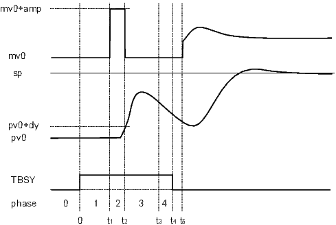
The block PIDMA extends the control function of the standard PID controller by the built in autotuning feature. Before start of the autotuner the operator have to reach the steady state of the process at a suitable working point (in manual or automatic mode) and specify the required type of the controller ittype (PI or PID) and other tuning parameters (iainf, DGC, tdg, tn, amp, dy and ispeed). The identification experiment is started by the input TUNE (input TBRK finishes the experiment). In this mode (), first of all the noise and possible drift gradient () are estimated during the user specified time () and then the rectangle pulse is applied to the input of the process and the first three process moments are identified from the pulse response. The amplitude of the pulse is set by the parameter amp. The pulse is finished when the process variable pv deviates from the steady value more than the dy threshold defines. The threshold is an absolute difference, therefore it is always a positive value. The duration of the tuning experiment depends on the dynamic behavior of the process. The remaining time to the end of the tuning is provided by the output trem.
If the identification experiment is properly finished () and the input ips is equal to zero, then the optimal parameters immediately appear on the block outputs pk, pti, ptd, pnd, pb, pc. In the opposite case () the output ite specifies the experiment error more closely. Other values of the ips input are reserved for custom specific purposes.
The function of the autotuner is illustrated in the following picture.

During the experiment, the output ite indicates the autotuner phases. In the phase of estimation of the response decay rate () the tuning experiment may be finished manually before its regular end. In this case the controller parameters are designed but the potential warning is indicated by setting the output ite=100.
At the end of the experiment (TBSY onoff), the function of the controller depends on the current controller mode. If the the designed controller parameters are immediately accepted.
Inputs
dv | Feedforward control variable | Double (F64) |
sp | Setpoint variable | Double (F64) |
pv | Process variable | Double (F64) |
tv | Tracking variable | Double (F64) |
hv | Manual value | Double (F64) |
MAN | Manual or automatic mode | Bool |
|
|
|
IH | Integrator hold | Bool |
|
|
|
TUNE | Start the tuning experiment (offon) or force transition to the next tuning phase (see the description of the ite output) | Bool |
TBRK | Stop the tuning experiment | Bool |
TAFF | Tuning affirmation; determines the way the computed parameters are handled | Bool |
|
|
|
ips | Meaning of the output signals pk, pti, ptd, pnd, pb and pc | Long (I32) |
|
|
|
Outputs
mv | Manipulated variable (controller output) | Double (F64) |
dmv | Controller velocity output (difference) | Double (F64) |
de | Deviation error | Double (F64) |
SAT | Saturation flag | Bool |
|
|
|
TBSY | Tuner busy flag | Bool |
TE | Tuning error | Bool |
|
|
|
ite | Error code | Long (I32) |
| Tuning error codes (after the experiment): |
|
|
|
|
| Tuning phases codes (during the experiment): |
|
|
|
|
| Remark about terminating the tuning phases |
|
|
|
|
trem | Estimated time to finish the tuning experiment [s] | Double (F64) |
pk | Proposed controller gain () | Double (F64) |
pti | Proposed integral time constant () | Double (F64) |
ptd | Proposed derivative time constant () | Double (F64) |
pnd | Proposed derivative component filtering () | Double (F64) |
pb | Proposed weighting factor – proportional component () | Double (F64) |
pc | Proposed weighting factor – derivative component () | Double (F64) |
Parameters
irtype | Controller type (control law) 6 | Long (I32) |
|
|
|
RACT | Reverse action flag | Bool |
|
|
|
k | Controller gain . By definition, the value 0 turns the controller off. Negative values are not allowed, use the RACT parameter for such a purpose. 0.0 1.0 | Double (F64) |
ti | Integral time constant . The value 0 disables the integrating part (the same effect as disabling it by the irtype parameter). 0.0 4.0 | Double (F64) |
td | Derivative time constant . The value 0 disables the derivative part (the same effect as disabling it by the irtype parameter). 0.0 1.0 | Double (F64) |
nd | Derivative filtering parameter . The value 0 disables the derivative part (the same effect as disabling it by the irtype parameter). 0.0 10.0 | Double (F64) |
b | Setpoint weighting – proportional part 0.0 2.0 1.0 | Double (F64) |
c | Setpoint weighting – derivative part 0.0 2.0 | Double (F64) |
tt | Tracking time constant. The value 0 stands for an implicit value, which is or (see above) for controllers with integrating part. For controllers without integrating part, the value 0 disables tracking. If tracking is needed for a P or PD controller, it can be enabled by entering a positive value greater than the sampling time. It is not possible to turn off tracking for controllers with the integrating part (due to the windup effect). 0.0 1.0 | Double (F64) |
hilim | Upper limit of the controller output 1.0 | Double (F64) |
lolim | Lower limit of the controller output -1.0 | Double (F64) |
dz | Dead zone | Double (F64) |
icotype | Controller output type 1 | Long (I32) |
|
|
|
ittype | Controller type to be designed 6 | Long (I32) |
|
|
|
iainf | Type of apriori information 1 | Long (I32) |
|
|
|
DGC | Drift gradient compensation on | Bool |
|
|
|
tdg | Drift gradient estimation time [s] 60.0 | Double (F64) |
tn | Length of noise estimation period [s] 5.0 | Double (F64) |
amp | Tuning pulse amplitude 0.5 | Double (F64) |
dy | Tuning pulse get down threshold (absolute difference from the steady pv value) 0.0 0.1 | Double (F64) |
ispeed | Desired closed loop speed 2 | Long (I32) |
|
|
|
ipid | PID controller form 1 | Long (I32) |
|
|
|
[Previous] [Back to top] [Up] [Next]
2024 © REX Controls s.r.o., www.rexygen.com