PIDU – PID controller unit
Block SymbolLicensing group: STANDARD

Function Description
The PIDU block is a basic block for creating a complete PID controller (or P, I, PI, PD, PID,
PI+S). In the most simple case it works as a standalone unit with the standard PID
controller functionality with two degrees of freedom. It can operate in automatic mode
() or manual
mode ().
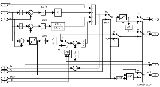
In the automatic mode (), the block PIDU implements the PID control law with two degrees of freedom in the form
where is Laplace transform of the manipulated variable mv, is Laplace transform of the setpoint variable sp, is Laplace transform of the process variable pv, is Laplace transform of the feedforward control variable dv and , , , , and are the parameters of the controller. The sign of the right hand side depends on the parameter RACT. The range of the manipulated variable mv (position controller output) is limited by parameters hilim, lolim. The parameter dz determines the dead zone in the integral part of the controller. The integral part of the control law can be switched off and fixed on the current value by the integrator hold input IH (). For the proper function of the controller it is necessary to connect the output mv of the controller to the controller input tv and properly set the tracking time constant tt.
The rule of thumb for a PID controller is . For a PI controller the formula is . In this way we obtain the bumpless operation of the controller in the case of the mode switching (manual, automatic) and also the correct operation of the controller when saturation of the output mv occurs (antiwindup).
By adjusting the tt parameter, it is possible to tune the behaviour at saturation limits (so-called bouncing from limits due to noise) and when switching multiple controllers (bump in the controller output occurs when switching controllers while the control error is non-zero).
The additional outputs dmv, de and SAT generate the velocity output (difference of mv), deviation error and saturation flag, respectively.
If the PIDU block is connected with the SCUV block to configure the 3-point step controller without the positional feedback, then the parameter icotype must be set to 4 and the meaning of the outputs mv and dmv and SAT is modified in the following way: mv and dmv give the PD part and difference of I part of the control law, respectively, and SAT provides the information for the SCUV block whether the deviation error is less than the dead zone dz in the automatic mode. In this case, the setpoint weighting factor c should be zero.
In the manual mode (), the input hv is copied to the output mv unless saturated. The overall control function of the PIDU block is quite clear from the following diagram:

Inputs
dv | Feedforward control variable | Double (F64) |
sp | Setpoint variable | Double (F64) |
pv | Process variable | Double (F64) |
tv | Tracking variable | Double (F64) |
hv | Manual value | Double (F64) |
MAN | Manual or automatic mode | Bool |
|
|
|
IH | Integrator hold | Bool |
|
|
|
Outputs
mv | Manipulated variable (controller output) | Double (F64) |
dmv | Controller velocity output (difference) | Double (F64) |
de | Deviation error | Double (F64) |
SAT | Saturation flag | Bool |
|
|
|
Parameters
irtype | Controller type (control law) 6 | Long (I32) |
|
|
|
RACT | Reverse action flag | Bool |
|
|
|
k | Controller gain . By definition, the value 0 turns the controller off. Negative values are not allowed, use the RACT parameter for such a purpose. 0.0 1.0 | Double (F64) |
ti | Integral time constant . The value 0 disables the integrating part (the same effect as disabling it by the irtype parameter). 0.0 4.0 | Double (F64) |
td | Derivative time constant . The value 0 disables the derivative part (the same effect as disabling it by the irtype parameter). 0.0 1.0 | Double (F64) |
nd | Derivative filtering parameter . The value 0 disables the derivative part (the same effect as disabling it by the irtype parameter). 0.0 10.0 | Double (F64) |
b | Setpoint weighting – proportional part 0.0 2.0 1.0 | Double (F64) |
c | Setpoint weighting – derivative part 0.0 2.0 | Double (F64) |
tt | Tracking time constant. The value 0 stands for an implicit value, which is or (see above) for controllers with integrating part. For controllers without integrating part, the value 0 disables tracking. If tracking is needed for a P or PD controller, it can be enabled by entering a positive value greater than the sampling time. It is not possible to turn off tracking for controllers with the integrating part (due to the windup effect). 0.0 1.0 | Double (F64) |
hilim | Upper limit of the controller output 1.0 | Double (F64) |
lolim | Lower limit of the controller output -1.0 | Double (F64) |
dz | Dead zone | Double (F64) |
icotype | Controller output type 1 | Long (I32) |
|
|
|
[Previous] [Back to top] [Up] [Next]
2024 © REX Controls s.r.o., www.rexygen.com